← Zpět na přehled PG2 / 02 Úvod

Odrazivost a rozptyl světla

  • Jiří Filip · ÚTIA AV ČR · ANI-PG2
  • Parametrizace a zachycení materiálů pomocí BRDF a BSSRDF.
  • Export PDF: 30. 9. 2026. Aktuální termín výuky není v rozcestníku uveden.
Původní autorský diagram: Odrazivost a rozptyl světla
Jiří Filip · původní diagram / ilustrace z PDF, strana 1
Původní snímek · 1Původní PDF strana 1

Jiří Filip · export PDF 30. 9. 2026 · PDF, strana 1

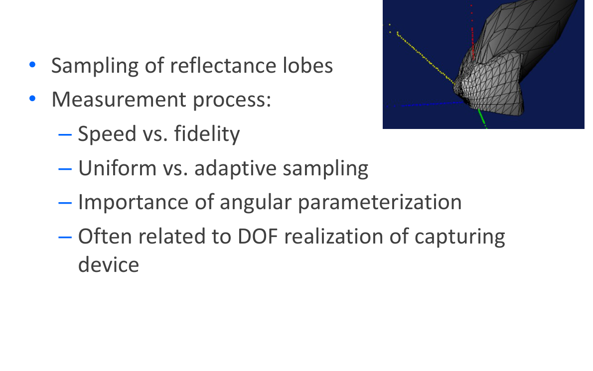
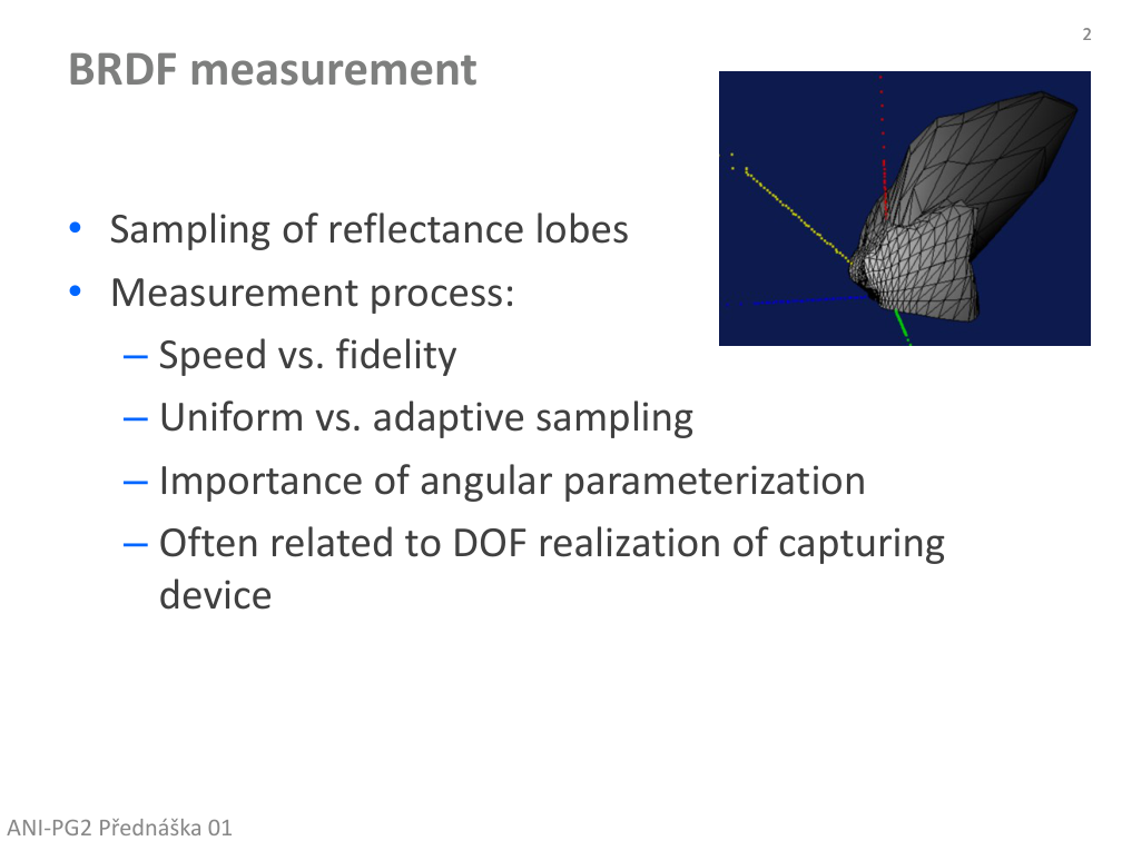
BRDF measurement

  • Sample the reflectance lobe rather than only a convenient set of directions.
  • Measurement balances acquisition speed and fidelity.
  • Uniform versus adaptive sampling, angular parameterization and the mechanical degrees of freedom of the capture device are linked.
Původní autorský diagram: BRDF measurement
Jiří Filip · původní diagram / ilustrace z PDF, strana 2
Původní snímek · 2Původní PDF strana 2

Jiří Filip · export PDF 30. 9. 2026 · PDF, strana 2

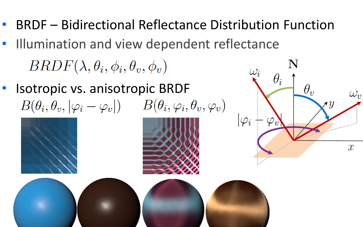
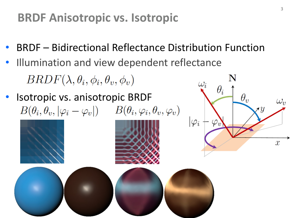
Isotropic and anisotropic BRDF

  • BRDF: Bidirectional Reflectance Distribution Function.
  • Reflectance depends on illumination and viewing directions.
  • For an isotropic material, a common rotation around the normal does not change reflectance; the relative azimuth matters.
  • Anisotropic materials retain orientation-dependent highlights.
Původní autorský diagram: Isotropic and anisotropic BRDF
Jiří Filip · původní diagram / ilustrace z PDF, strana 3
Původní snímek · 3Původní PDF strana 3

Jiří Filip · export PDF 30. 9. 2026 · PDF, strana 3

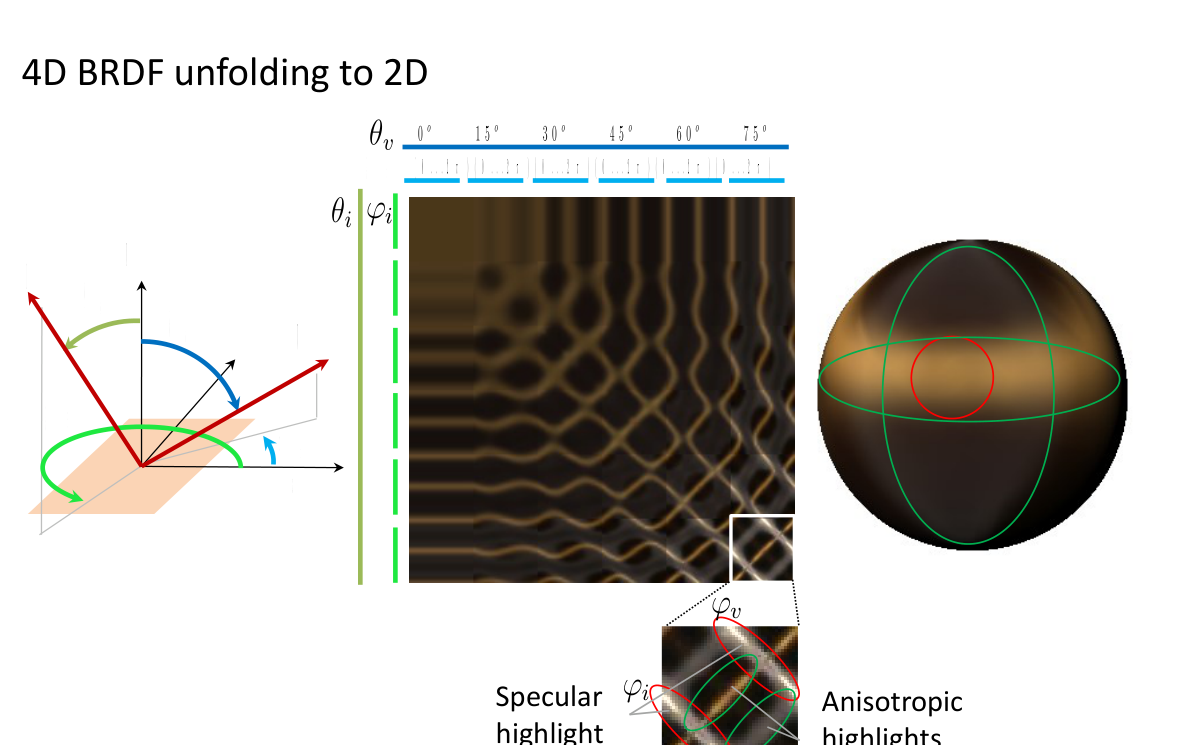
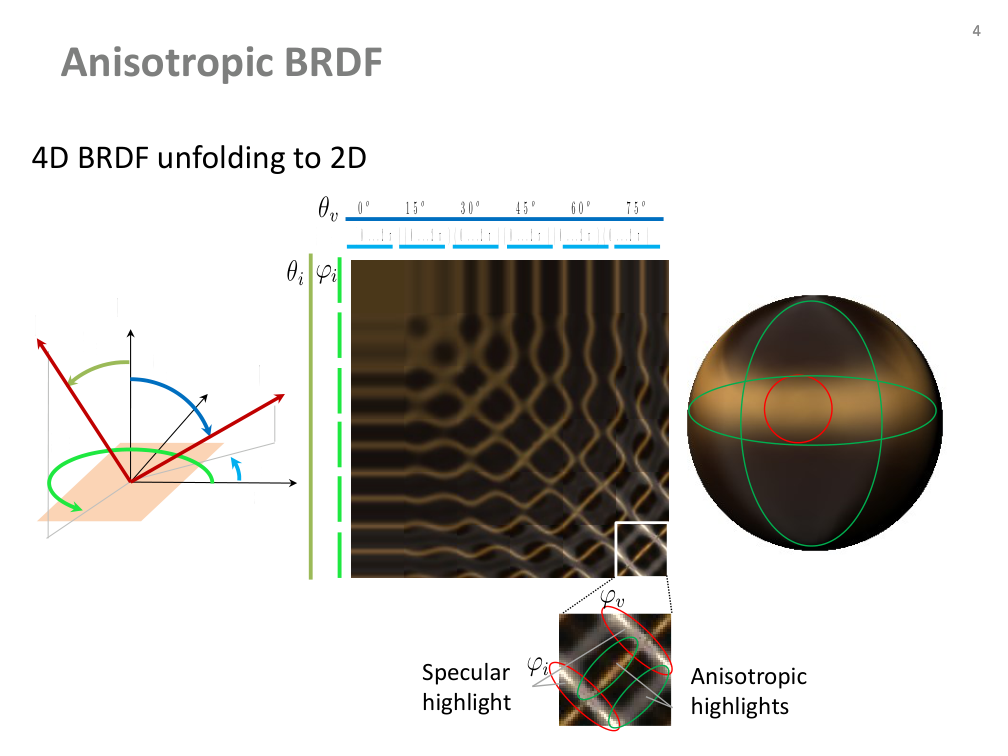
Anisotropic BRDF: unfolding 4D data

  • Four angular coordinates: incident and viewing polar/azimuth angles.
  • The author unfolds the angular domain into a 2D visualization.
  • Compare a specular highlight with anisotropic highlights across the slices.
Původní autorský diagram: Anisotropic BRDF: unfolding 4D data
Jiří Filip · původní diagram / ilustrace z PDF, strana 4
Původní snímek · 4Původní PDF strana 4

Jiří Filip · export PDF 30. 9. 2026 · PDF, strana 4

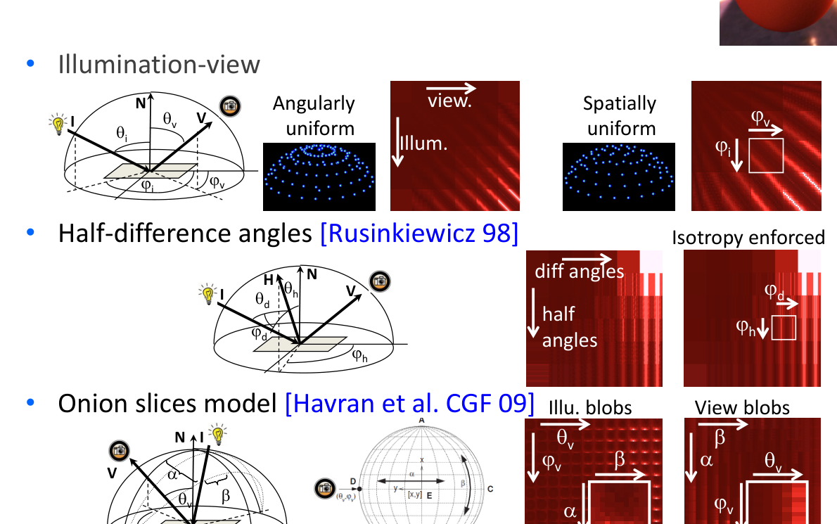
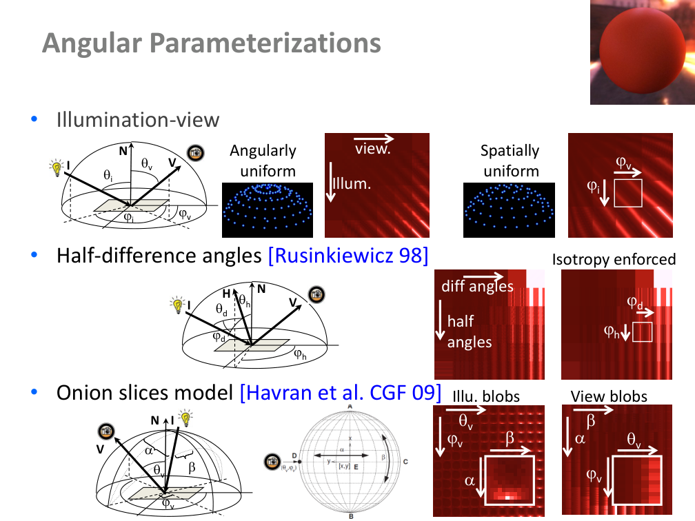
Angular parameterizations

  • Illumination–view angles directly describe the light and camera directions.
  • Half–difference angles: Rusinkiewicz (1998).
  • Onion-slices model: Havran et al.; compare spatially uniform and angularly uniform sampling in the original diagrams.
Původní autorský diagram: Angular parameterizations
Jiří Filip · původní diagram / ilustrace z PDF, strana 5
Původní snímek · 5Původní PDF strana 5

Jiří Filip · export PDF 30. 9. 2026 · PDF, strana 5

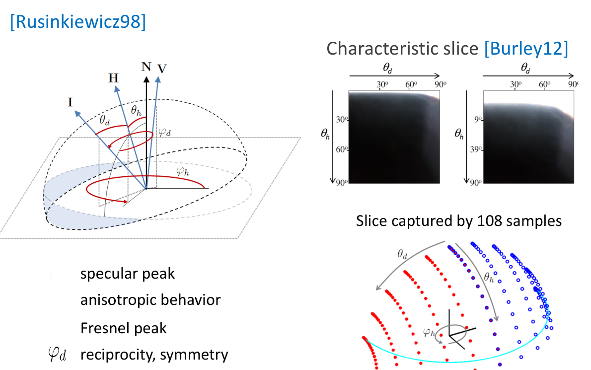
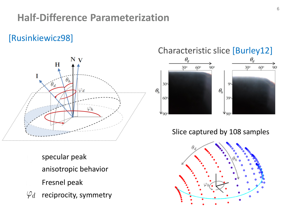
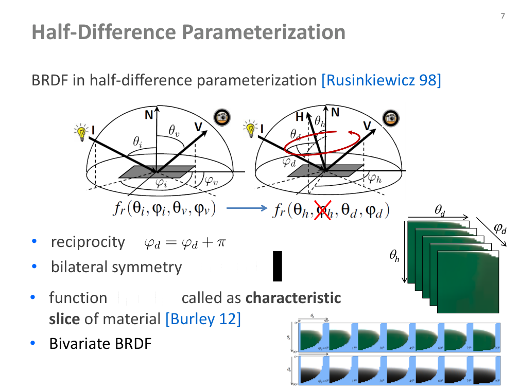
Half–difference parameterization

  • The half vector describes the orientation halfway between illumination and view.
  • The source distinguishes specular-peak, anisotropy, Fresnel-peak, reciprocity and symmetry behaviour.
  • Burley’s characteristic slice is illustrated with a capture using 108 samples.
Původní autorský diagram: Half–difference parameterization
Jiří Filip · původní diagram / ilustrace z PDF, strana 6
Původní snímek · 6Původní PDF strana 6

Jiří Filip · export PDF 30. 9. 2026 · PDF, strana 6

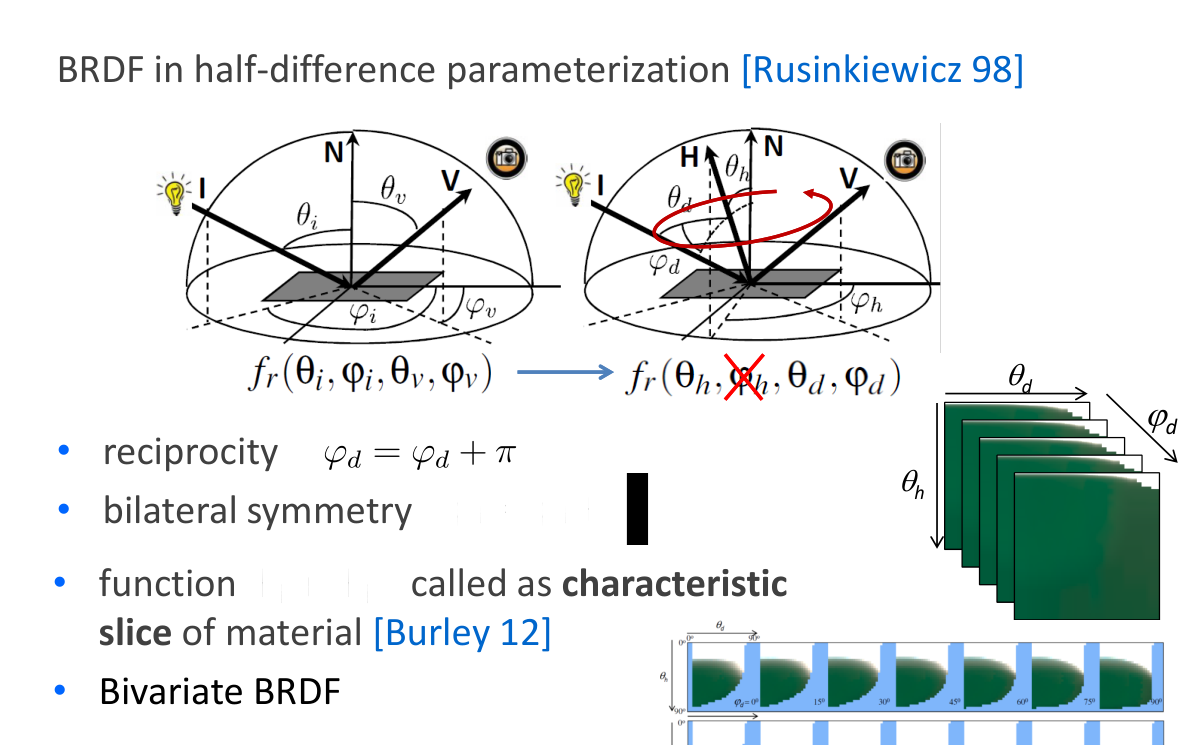
Characteristic slices and symmetry

  • Reparameterize fᵣ(θᵢ, φᵢ, θᵥ, φᵥ) using half and difference angles.
  • Isotropic behaviour removes dependence on the common half-vector azimuth.
  • The author illustrates reciprocity, bilateral symmetry and bivariate BRDF slices (Rusinkiewicz 1998; Burley 2012).
Původní autorský diagram: Characteristic slices and symmetry
Jiří Filip · původní diagram / ilustrace z PDF, strana 7
Původní snímek · 7Původní PDF strana 7

Jiří Filip · export PDF 30. 9. 2026 · PDF, strana 7

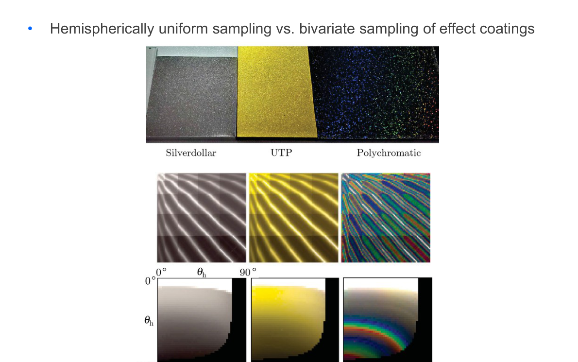
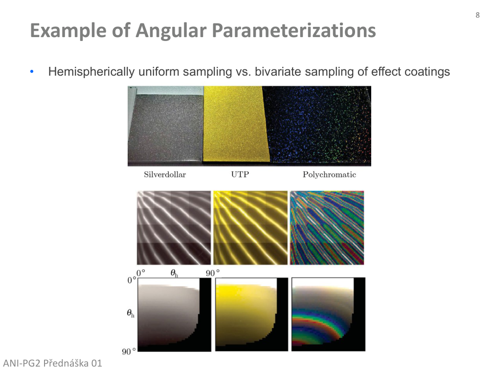
Comparing angular parameterizations

  • Hemispherically uniform sampling versus bivariate sampling of effect coatings.
  • Compare the source photographs: a different angular grid can capture or miss important appearance changes.
Původní autorský diagram: Comparing angular parameterizations
Jiří Filip · původní diagram / ilustrace z PDF, strana 8
Původní snímek · 8Původní PDF strana 8

Jiří Filip · export PDF 30. 9. 2026 · PDF, strana 8

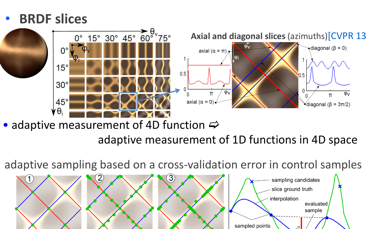
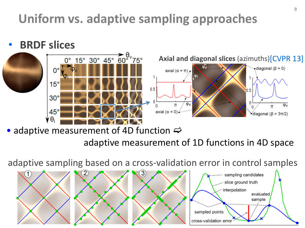
Uniform and adaptive sampling

  • The source compares axial and diagonal BRDF slices.
  • Adaptive sampling may operate on the 4D function or along 1D functions embedded in that space.
  • The cited CVPR 2013 method uses cross-validation error at control samples.
  • The GRAFIT example below is a separate synthetic 1D illustration, not that measurement method.
Původní autorský diagram: Uniform and adaptive sampling
Jiří Filip · původní diagram / ilustrace z PDF, strana 9
Původní snímek · 9Původní PDF strana 9

Jiří Filip · export PDF 30. 9. 2026 · PDF, strana 9

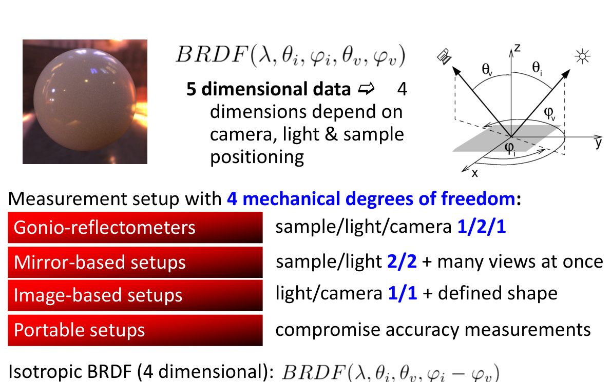
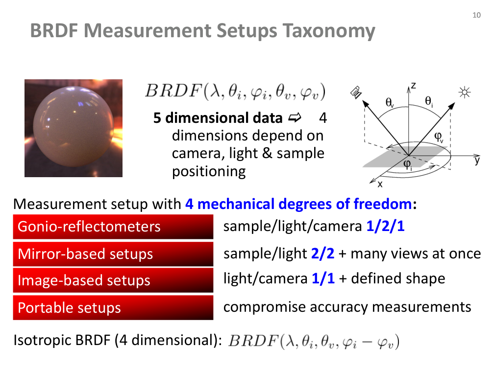
BRDF measurement setups: taxonomy

  • Gonio-reflectometers, mirror-based setups, image-based setups and portable setups.
  • Mechanical positioning may distribute four angular degrees of freedom among the sample, light and camera.
  • The source’s 5D/4D data labels include spectral dependence; at a fixed wavelength the anisotropic angular domain is 4D (isotropic: 3D).
  • Capture accuracy and practical portability involve different compromises.
Původní autorský diagram: BRDF measurement setups: taxonomy
Jiří Filip · původní diagram / ilustrace z PDF, strana 10
Původní snímek · 10Původní PDF strana 10

Jiří Filip · export PDF 30. 9. 2026 · PDF, strana 10

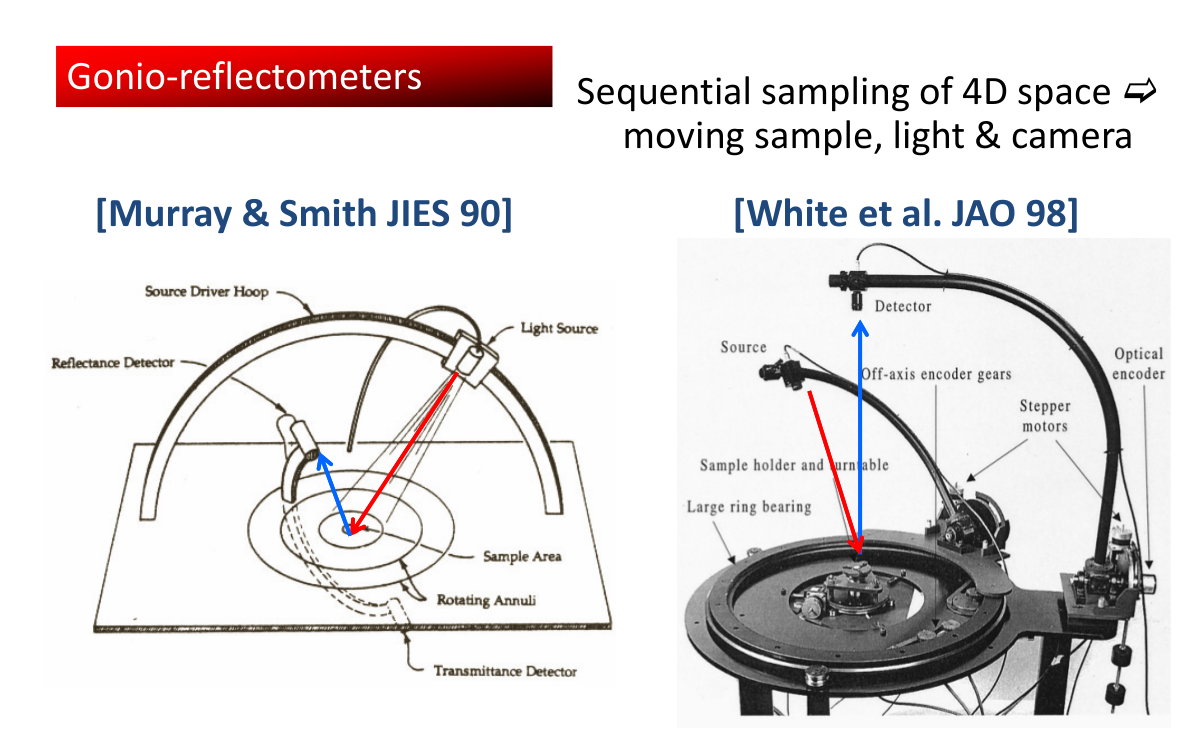
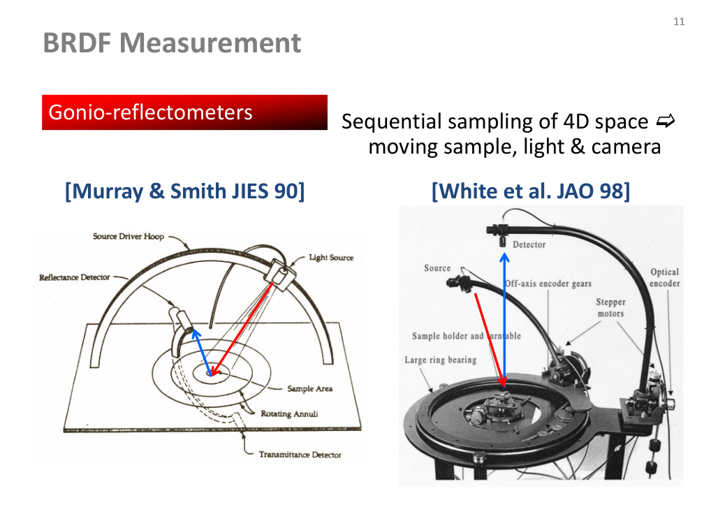
Gonio-reflectometers

  • Sequential sampling moves the sample, light and camera through the angular domain.
  • The source shows Murray & Smith (1990) and White et al. (1998).
Původní autorský diagram: Gonio-reflectometers
Jiří Filip · původní diagram / ilustrace z PDF, strana 11
Původní snímek · 11Původní PDF strana 11

Jiří Filip · export PDF 30. 9. 2026 · PDF, strana 11

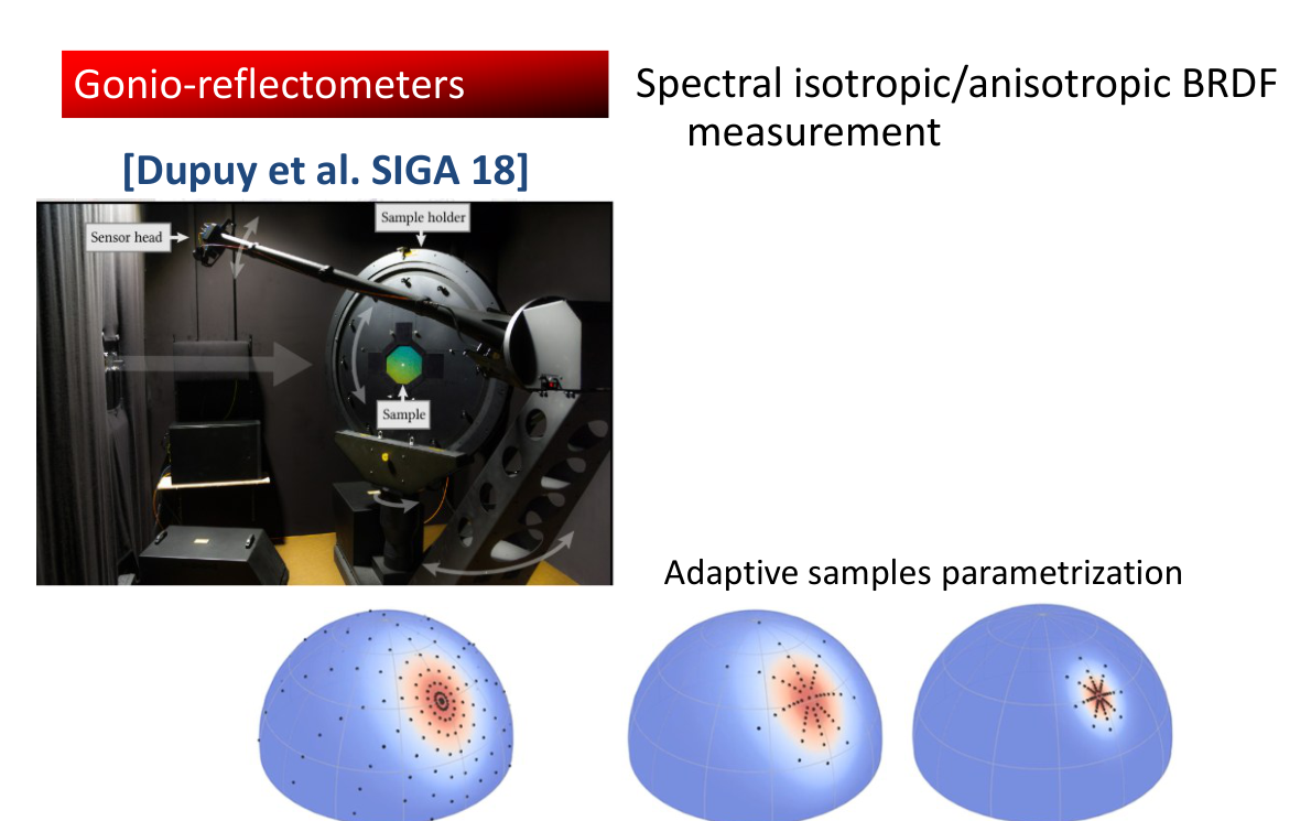
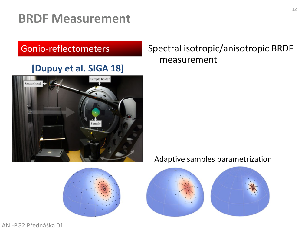
Spectral and adaptive gonio-reflectometry

  • Spectral isotropic/anisotropic BRDF measurement.
  • Dupuy et al. (2018): adaptive sample parameterization; compare the device and sampling diagrams.
Původní autorský diagram: Spectral and adaptive gonio-reflectometry
Jiří Filip · původní diagram / ilustrace z PDF, strana 12
Původní snímek · 12Původní PDF strana 12

Jiří Filip · export PDF 30. 9. 2026 · PDF, strana 12

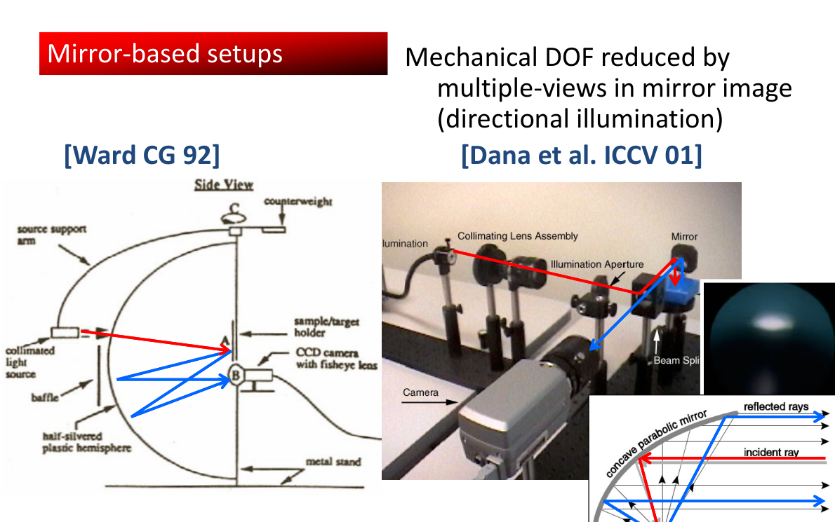
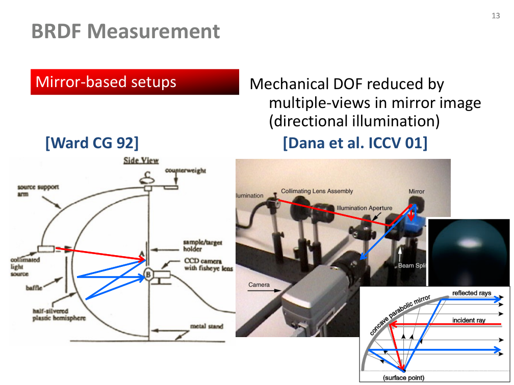
Mirror-based setups: directional illumination

  • Multiple views in a mirror image reduce mechanical degrees of freedom.
  • The author compares Ward (1992) and Dana et al. (2001).
Původní autorský diagram: Mirror-based setups: directional illumination
Jiří Filip · původní diagram / ilustrace z PDF, strana 13
Původní snímek · 13Původní PDF strana 13

Jiří Filip · export PDF 30. 9. 2026 · PDF, strana 13

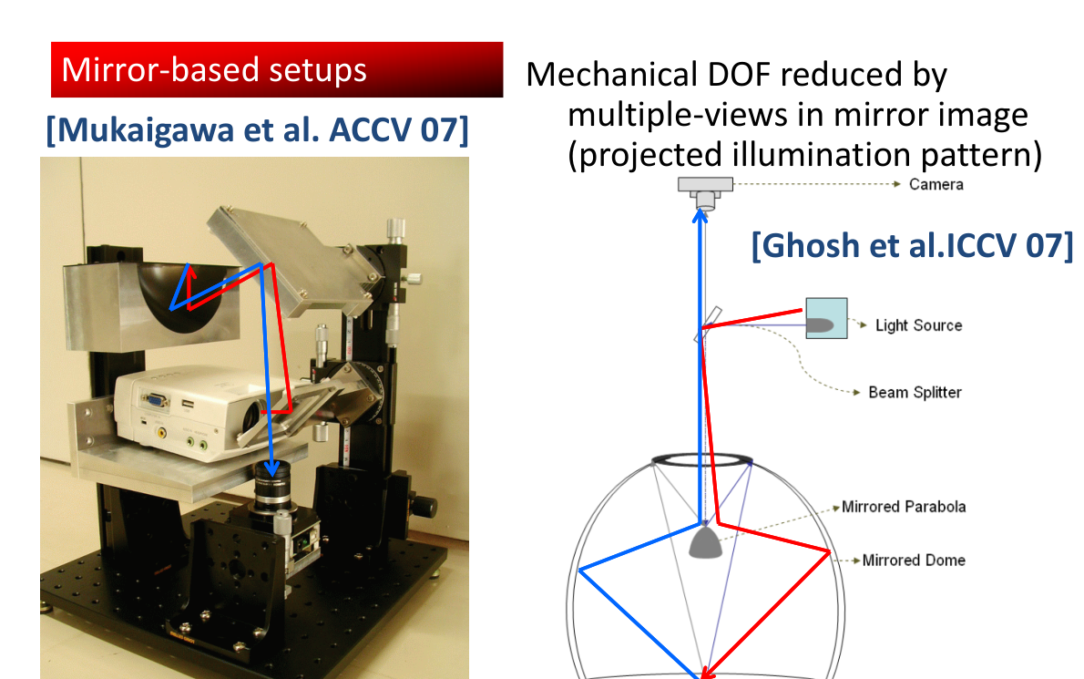
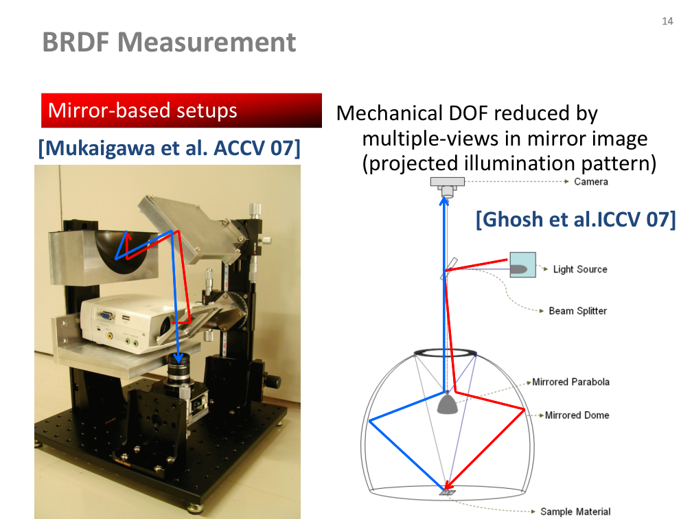
Mirror-based setups: projected illumination

  • Projected illumination patterns provide another route to reducing mechanical motion.
  • Source examples: Mukaigawa et al. (2007) and Ghosh et al. (2007).
Původní autorský diagram: Mirror-based setups: projected illumination
Jiří Filip · původní diagram / ilustrace z PDF, strana 14
Původní snímek · 14Původní PDF strana 14

Jiří Filip · export PDF 30. 9. 2026 · PDF, strana 14

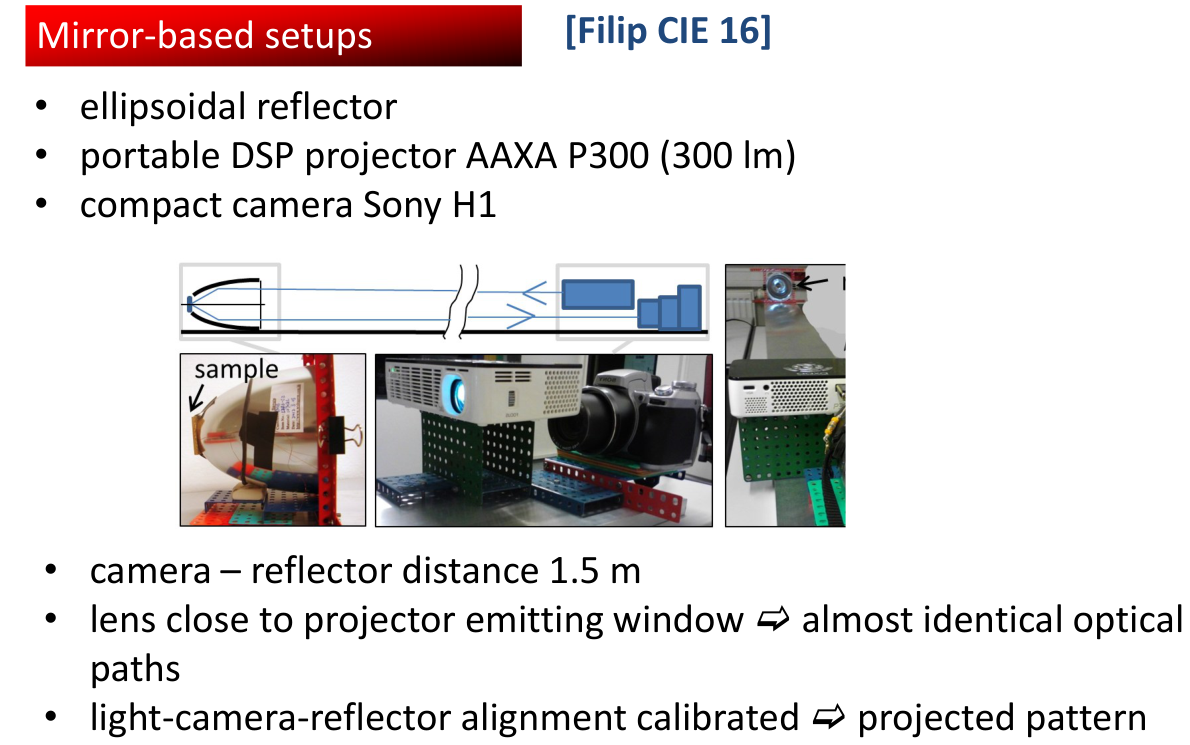
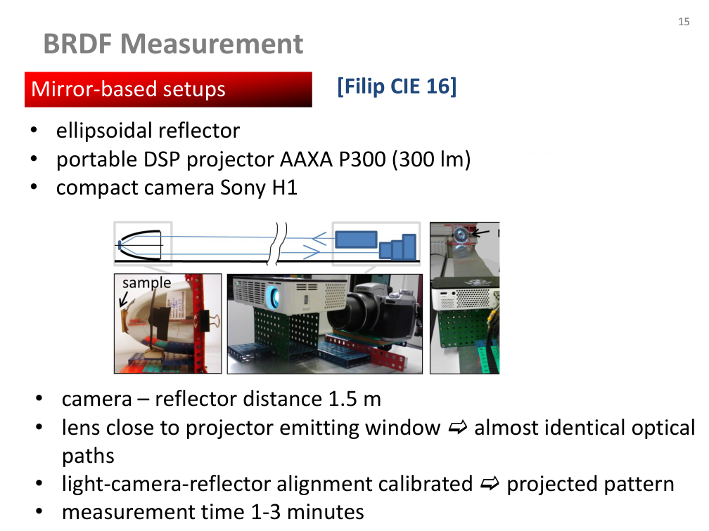
Ellipsoidal-reflector prototype

  • Filip (CIE 2016): ellipsoidal reflector, AAXA P300 projector (300 lm), Sony H1 camera.
  • Camera–reflector distance: 1.5 m. A lens close to the projector window gives nearly identical optical paths.
  • Calibrate the light–camera–reflector alignment using a projected pattern.
  • The reported measurement time is 1–3 minutes for this source setup.
Původní autorský diagram: Ellipsoidal-reflector prototype
Jiří Filip · původní diagram / ilustrace z PDF, strana 15
Původní snímek · 15Původní PDF strana 15

Jiří Filip · export PDF 30. 9. 2026 · PDF, strana 15

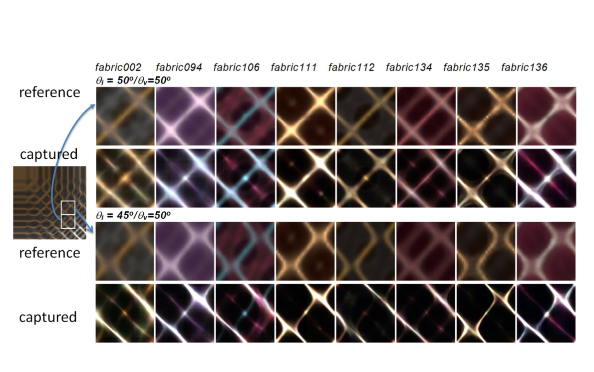
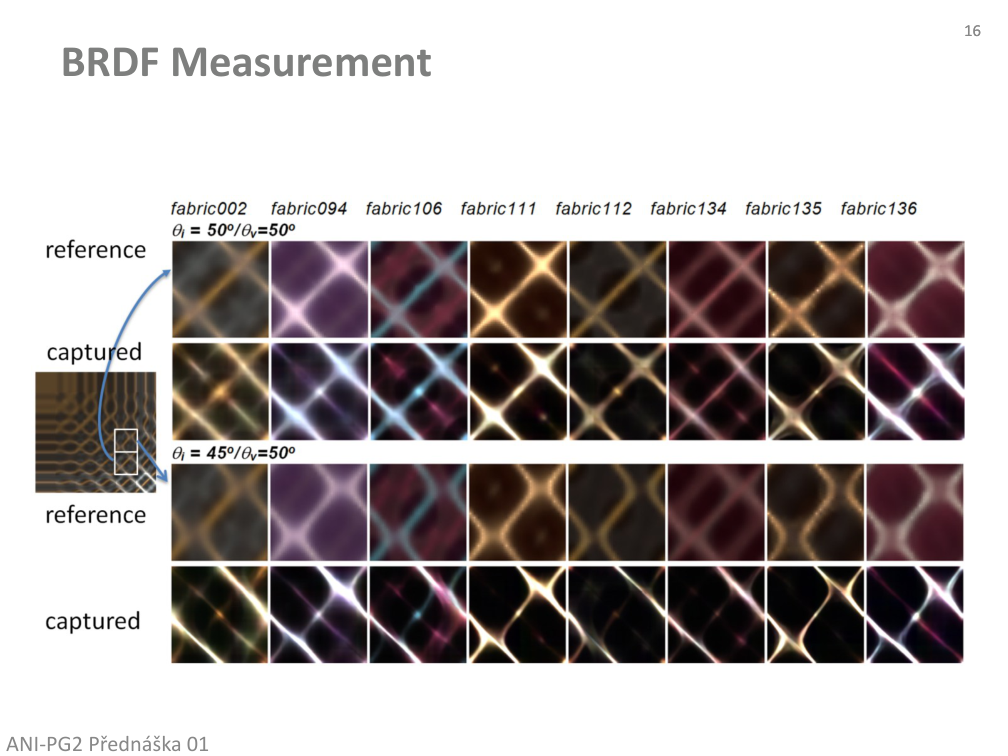
Measured and reference appearances

  • The author compares measured results and reference photographs for several materials.
  • Inspect highlight shape and structure across rows and columns in the original illustration.
Původní autorský diagram: Measured and reference appearances
Jiří Filip · původní diagram / ilustrace z PDF, strana 16
Původní snímek · 16Původní PDF strana 16

Jiří Filip · export PDF 30. 9. 2026 · PDF, strana 16

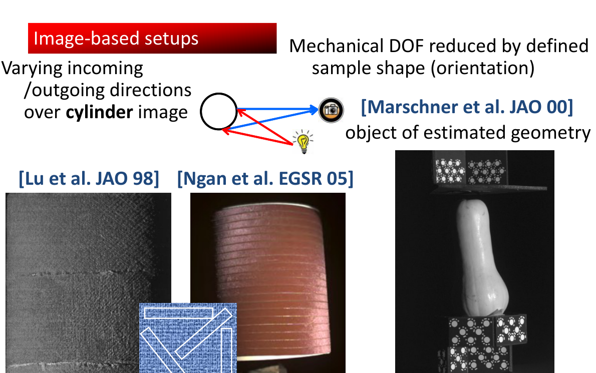
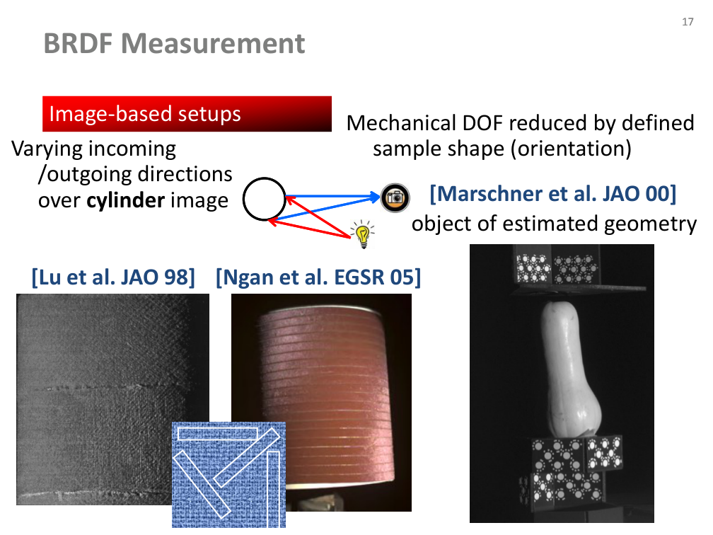
Image-based setups: known shape

  • A defined sample shape constrains surface orientation and reduces required mechanical motion.
  • A cylinder image contains varying incoming/outgoing directions (Lu et al. 1998).
  • Other examples use estimated geometry (Marschner et al. 2000; Ngan et al. 2005).
Původní autorský diagram: Image-based setups: known shape
Jiří Filip · původní diagram / ilustrace z PDF, strana 17
Původní snímek · 17Původní PDF strana 17

Jiří Filip · export PDF 30. 9. 2026 · PDF, strana 17

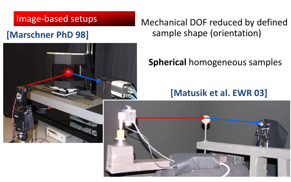
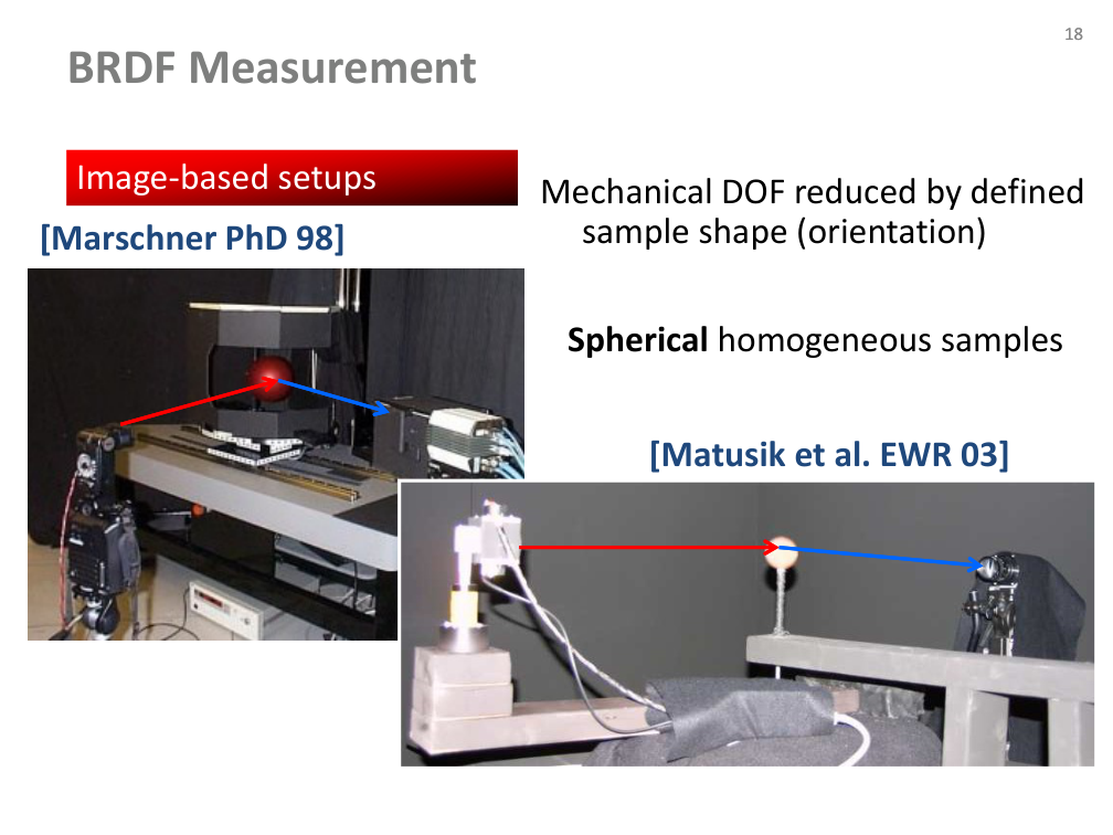
Image-based setups: spheres

  • Spherical, homogeneous samples expose many orientations in an image.
  • The source compares Marschner (1998) and Matusik et al. (2003).
Původní autorský diagram: Image-based setups: spheres
Jiří Filip · původní diagram / ilustrace z PDF, strana 18
Původní snímek · 18Původní PDF strana 18

Jiří Filip · export PDF 30. 9. 2026 · PDF, strana 18

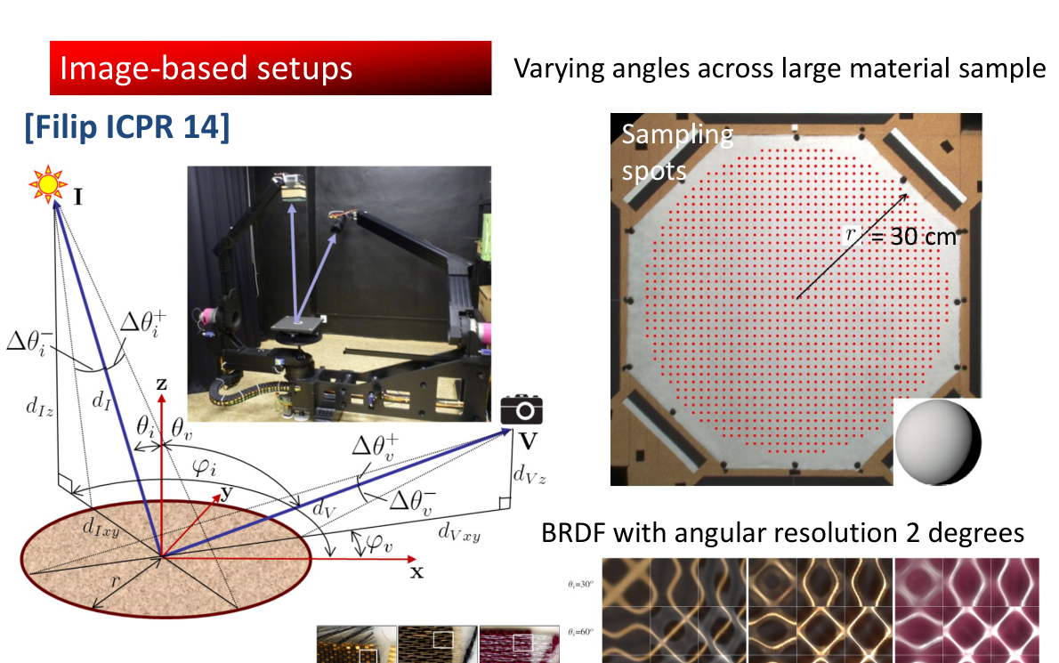
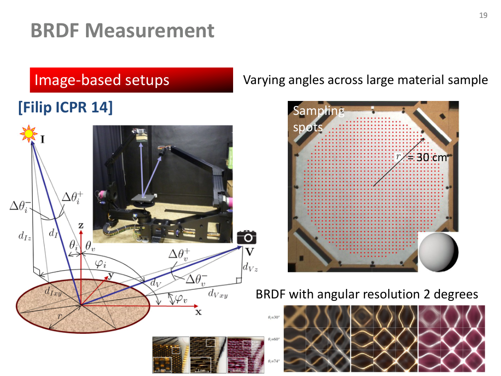
Image-based setups: a large sample

  • Varying angles across a large material sample (Filip, ICPR 2014).
  • The source describes a 30 cm sample and an angular resolution of 2°.
  • Sampling spots and capture geometry are shown in the diagram.
Původní autorský diagram: Image-based setups: a large sample
Jiří Filip · původní diagram / ilustrace z PDF, strana 19
Původní snímek · 19Původní PDF strana 19

Jiří Filip · export PDF 30. 9. 2026 · PDF, strana 19

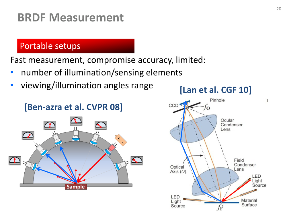
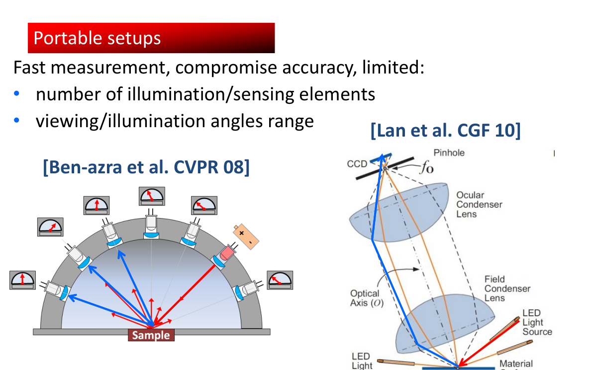
Portable setups

  • Faster and more portable capture compromises angular coverage and accuracy.
  • Important limits: the number of illumination/sensing elements and the range of viewing/illumination angles.
  • Source examples: Ben-Ezra et al. (2008) and Lan et al. (2010).
Původní autorský diagram: Portable setups
Jiří Filip · původní diagram / ilustrace z PDF, strana 20
Původní snímek · 20Původní PDF strana 20

Jiří Filip · export PDF 30. 9. 2026 · PDF, strana 20

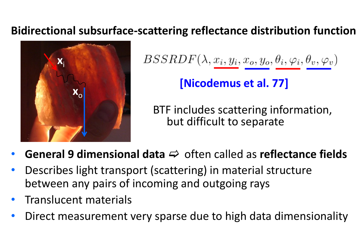
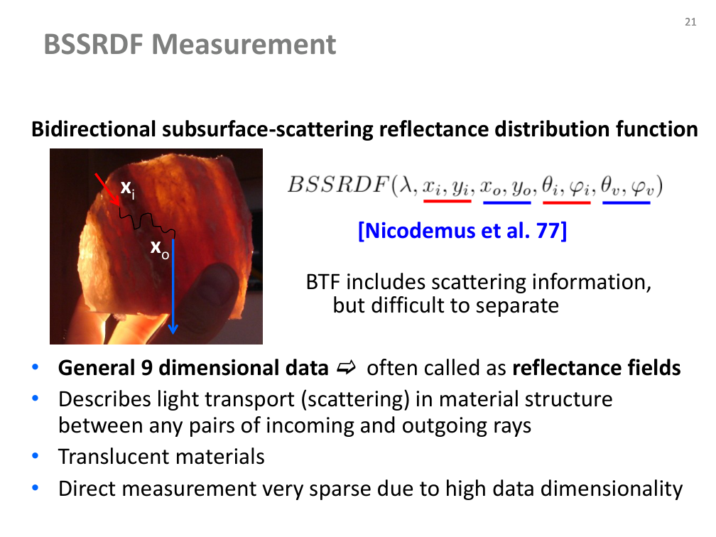
BSSRDF: subsurface light transport

  • Bidirectional subsurface-scattering reflectance distribution function (Nicodemus et al. 1977).
  • Scattering transports light between distinct incident and outgoing positions and directions.
  • The source describes general 9D data / reflectance fields and sparse direct measurement due to dimensionality.
  • BTF includes scattering effects, but separating them is difficult.
Původní autorský diagram: BSSRDF: subsurface light transport
Jiří Filip · původní diagram / ilustrace z PDF, strana 21
Původní snímek · 21Původní PDF strana 21

Jiří Filip · export PDF 30. 9. 2026 · PDF, strana 21

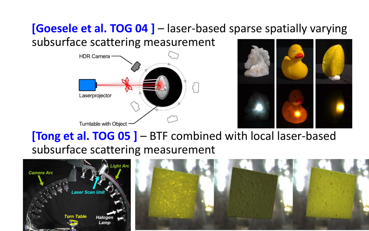
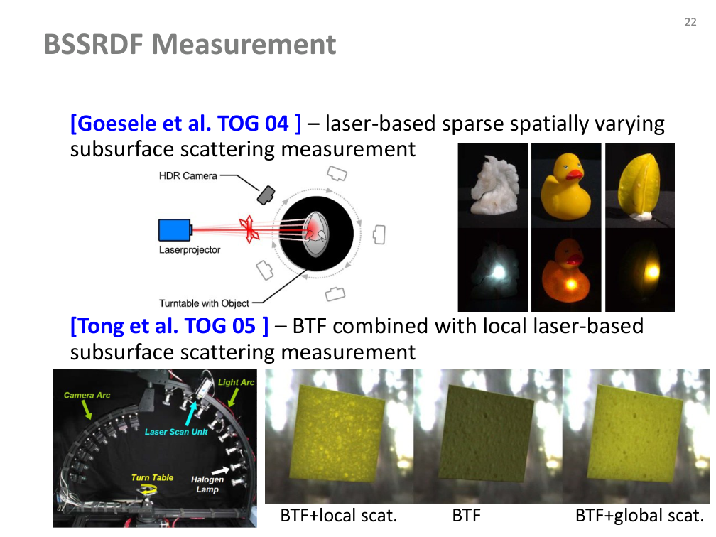
Measuring spatially varying scattering

  • Goesele et al. (2004): sparse laser-based subsurface-scattering measurements.
  • Tong et al. (2005): BTF combined with local laser measurements.
  • Compare BTF alone, BTF with local scattering, and BTF with global scattering.
Původní autorský diagram: Measuring spatially varying scattering
Jiří Filip · původní diagram / ilustrace z PDF, strana 22
Původní snímek · 22Původní PDF strana 22

Jiří Filip · export PDF 30. 9. 2026 · PDF, strana 22

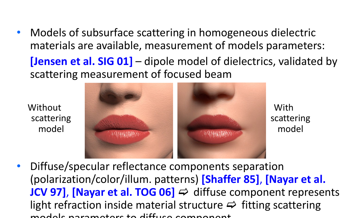
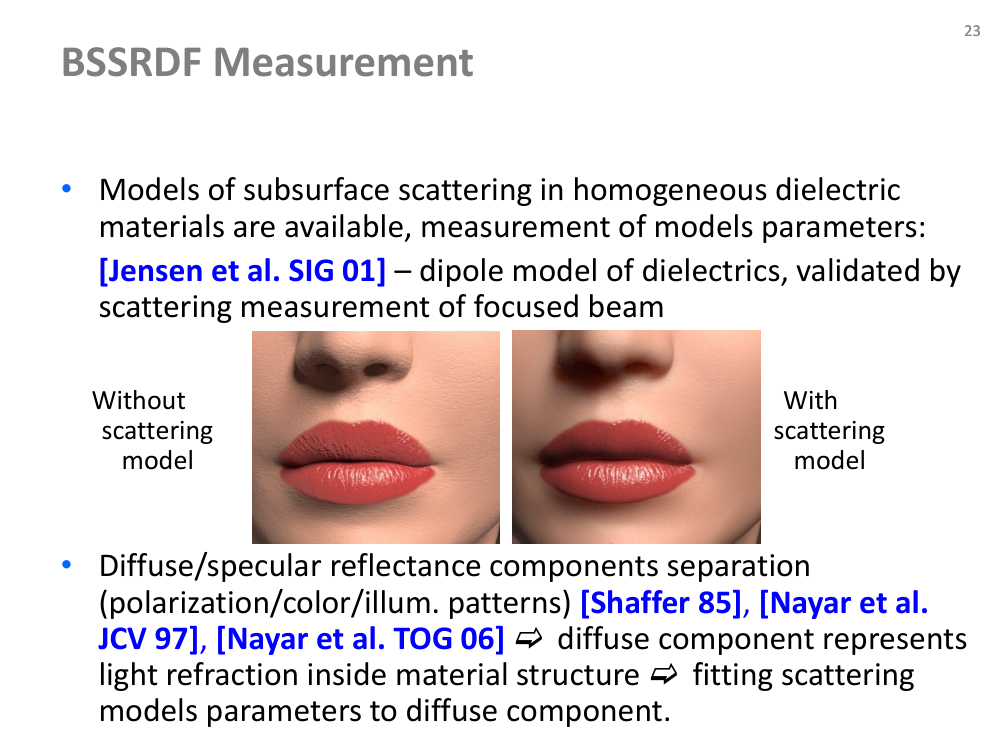
Fitting scattering models

  • Homogeneous dielectric materials can be described by subsurface-scattering models.
  • Jensen et al. (2001): a dipole model validated with a focused beam.
  • Separate diffuse and specular components using polarization, colour or illumination patterns; the diffuse component supports fitting scattering parameters.
  • Source references include Shafer (1985) and Nayar et al. (1997, 2006).
Původní autorský diagram: Fitting scattering models
Jiří Filip · původní diagram / ilustrace z PDF, strana 23
Původní snímek · 23Původní PDF strana 23

Jiří Filip · export PDF 30. 9. 2026 · PDF, strana 23

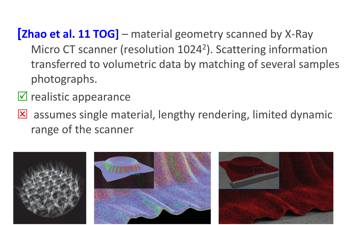
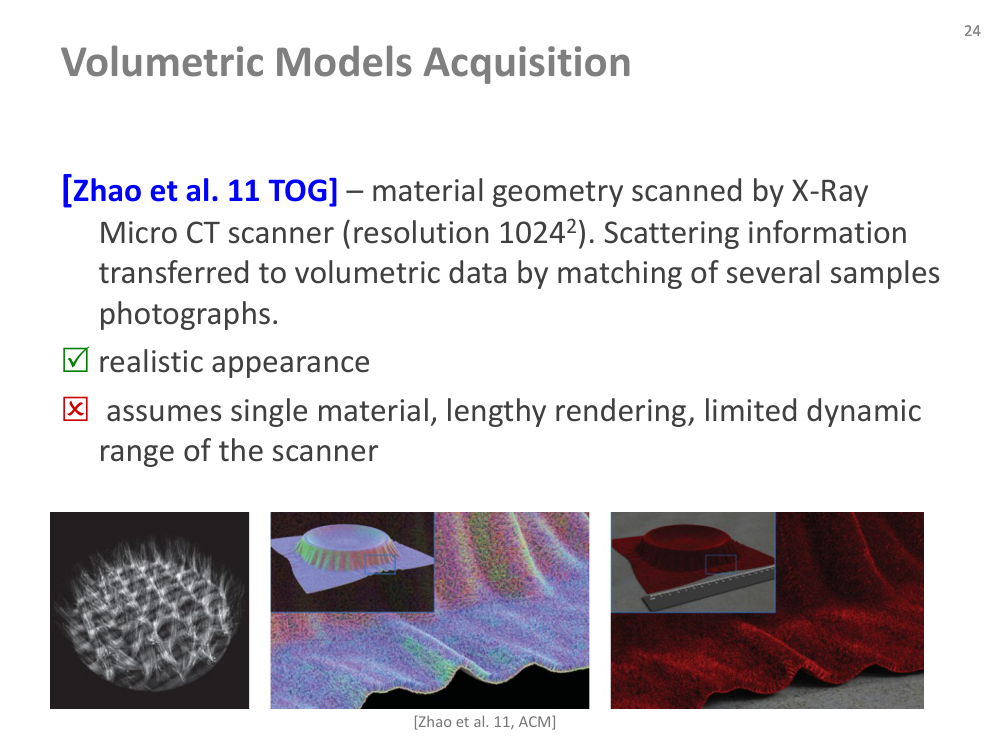
Volumetric model acquisition

  • Zhao et al. (2011): micro-CT geometry combined with optical scattering information fitted to sample photographs.
  • Benefit: realistic material appearance.
  • Limits in the source: one assumed material, lengthy rendering and the scanner’s limited dynamic range.
  • The resolution notation in the PDF is retained in its original illustration rather than guessed from damaged text extraction.
Původní autorský diagram: Volumetric model acquisition
Jiří Filip · původní diagram / ilustrace z PDF, strana 24
Původní snímek · 24Původní PDF strana 24

Jiří Filip · export PDF 30. 9. 2026 · PDF, strana 24

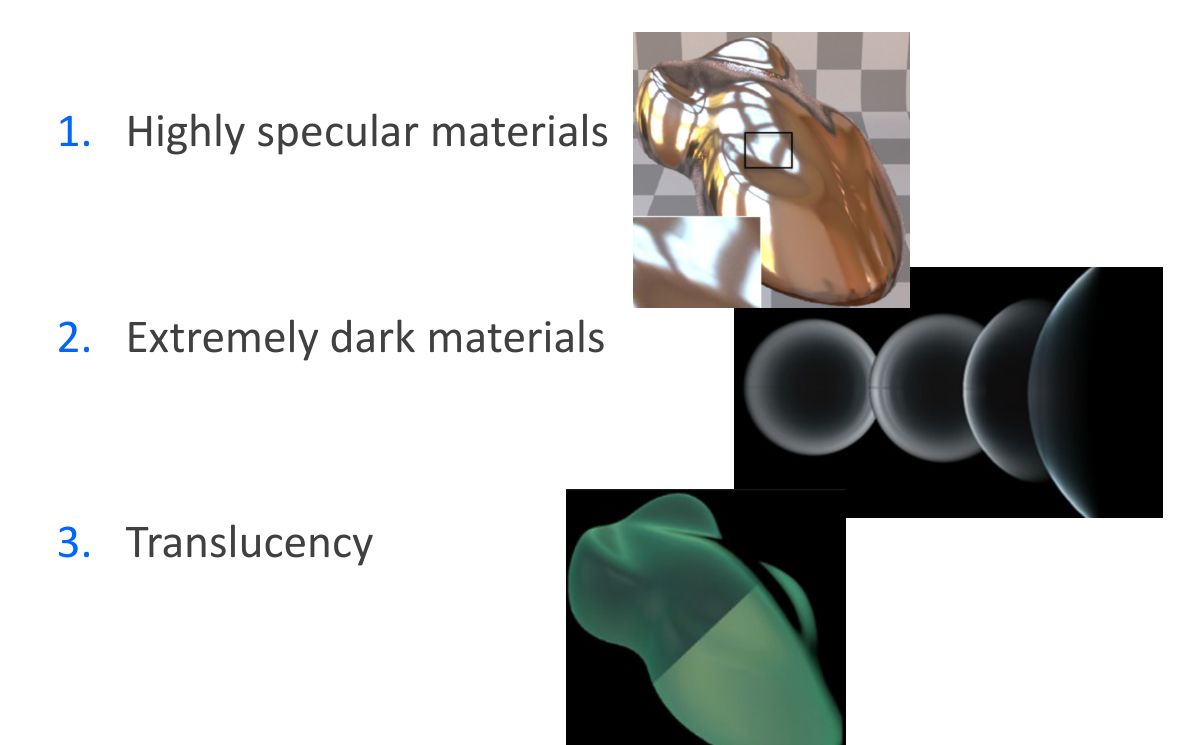
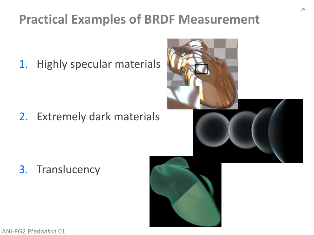
Practical BRDF measurement examples

  • Highly specular materials.
  • Extremely dark materials.
  • Translucency.
Původní autorský diagram: Practical BRDF measurement examples
Jiří Filip · původní diagram / ilustrace z PDF, strana 25
Původní snímek · 25Původní PDF strana 25

Jiří Filip · export PDF 30. 9. 2026 · PDF, strana 25

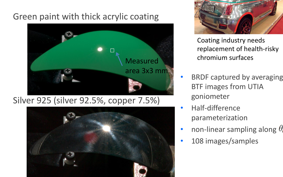
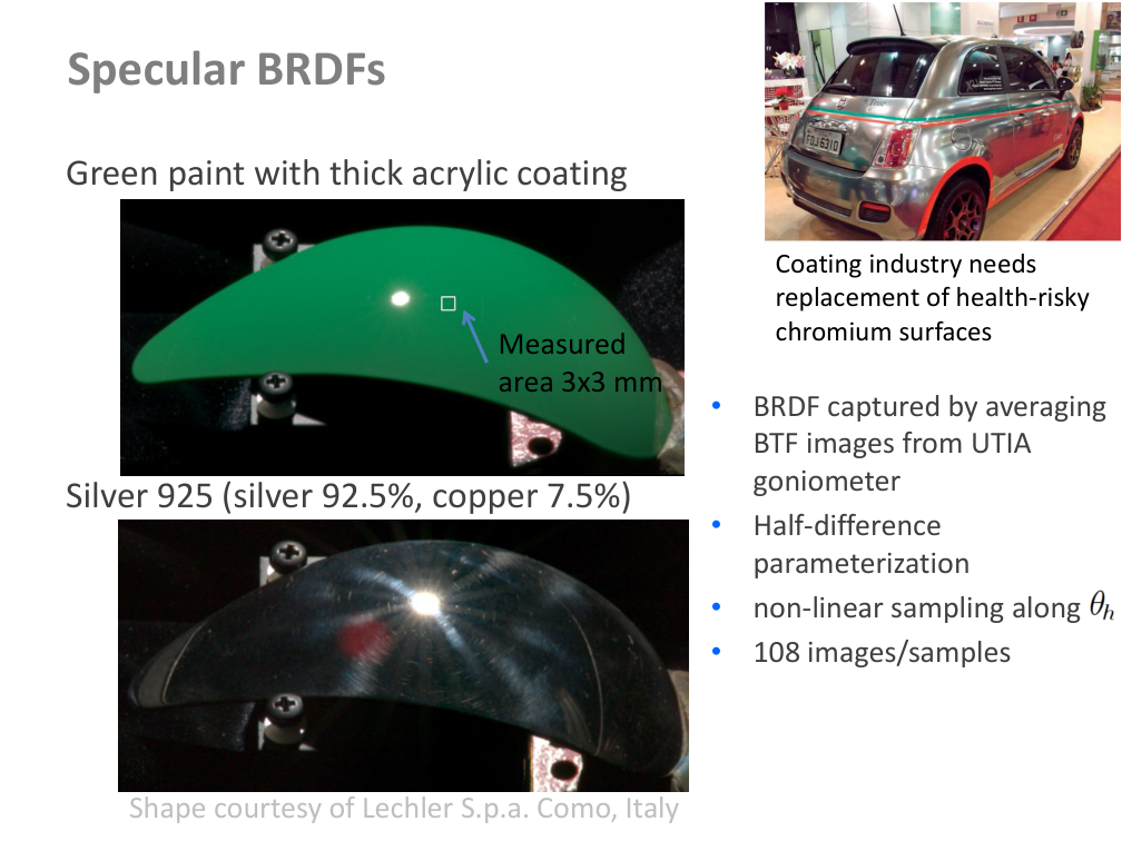
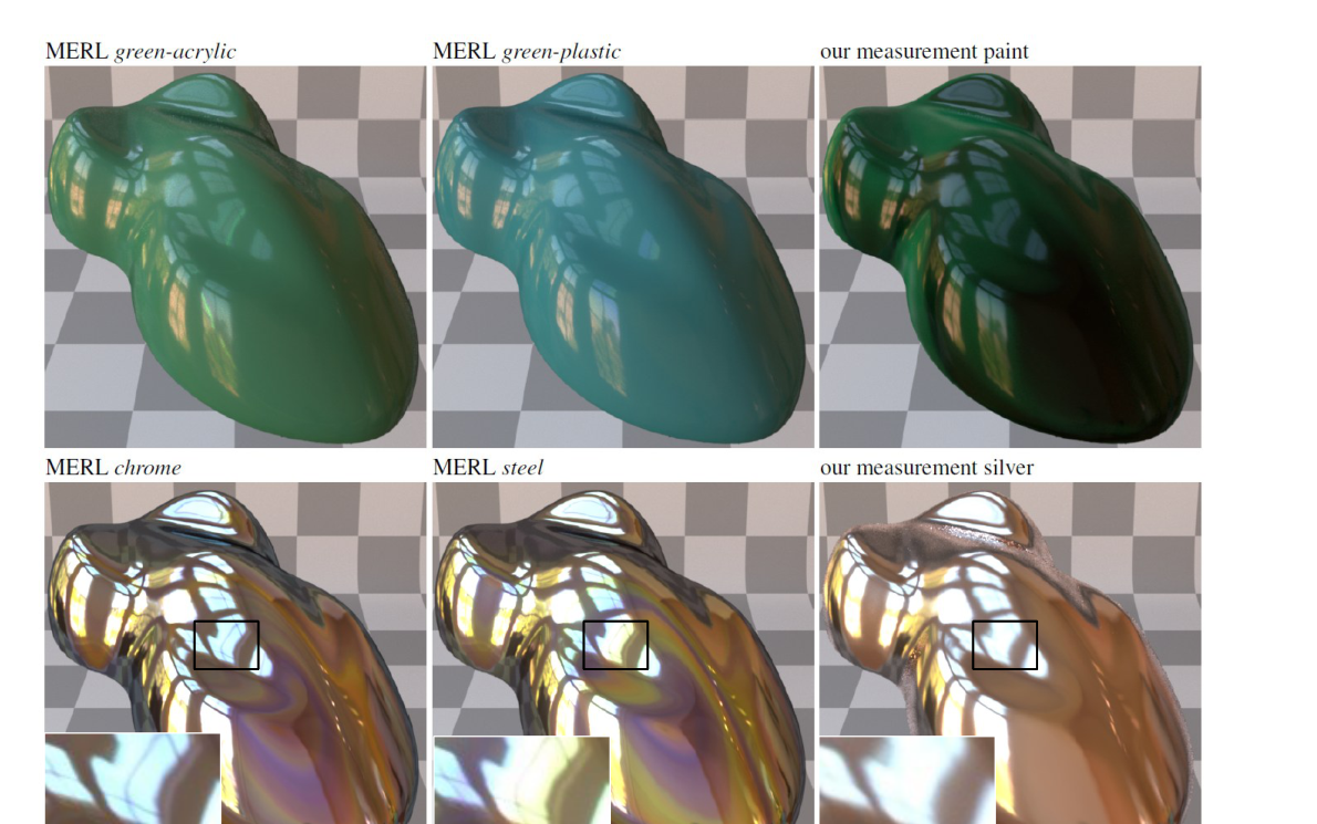
Specular materials: capture strategy

  • Green paint with a thick acrylic coating and silver 925 (92.5% silver, 7.5% copper).
  • BRDF is obtained by averaging BTF images from the UTIA goniometer.
  • Half–difference parameterization and nonlinear angular sampling; the source describes 108 images/samples.
  • Measured area: 3 × 3 mm. Shape courtesy of Lechler S.p.a., Como, Italy.
Původní autorský diagram: Specular materials: capture strategy
Jiří Filip · původní diagram / ilustrace z PDF, strana 26
Původní snímek · 26Původní PDF strana 26

Jiří Filip · export PDF 30. 9. 2026 · PDF, strana 26

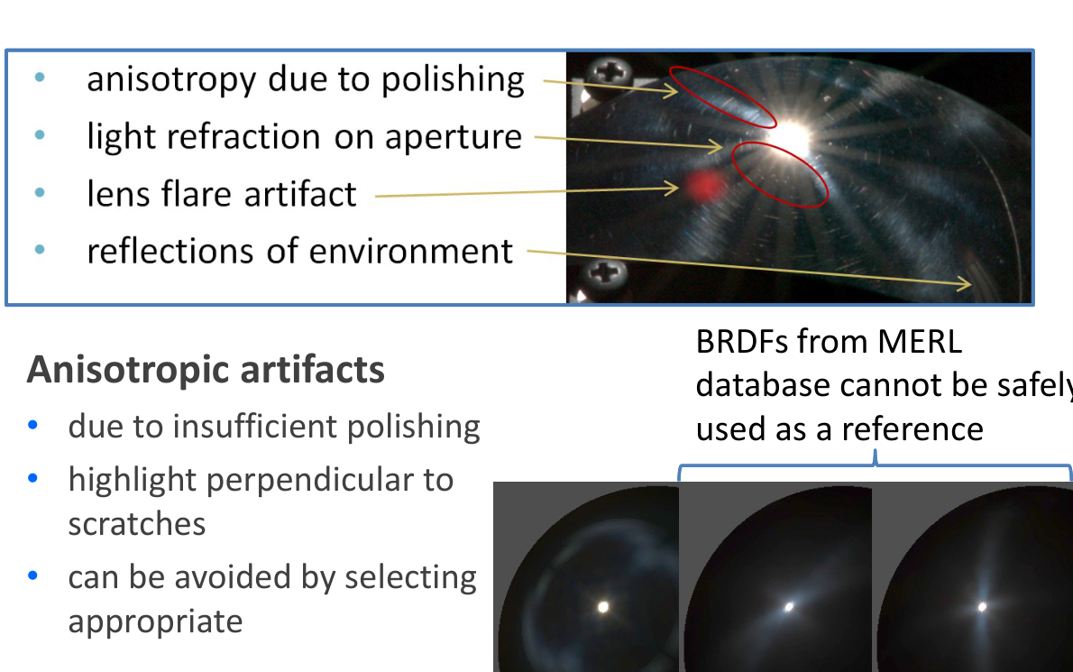
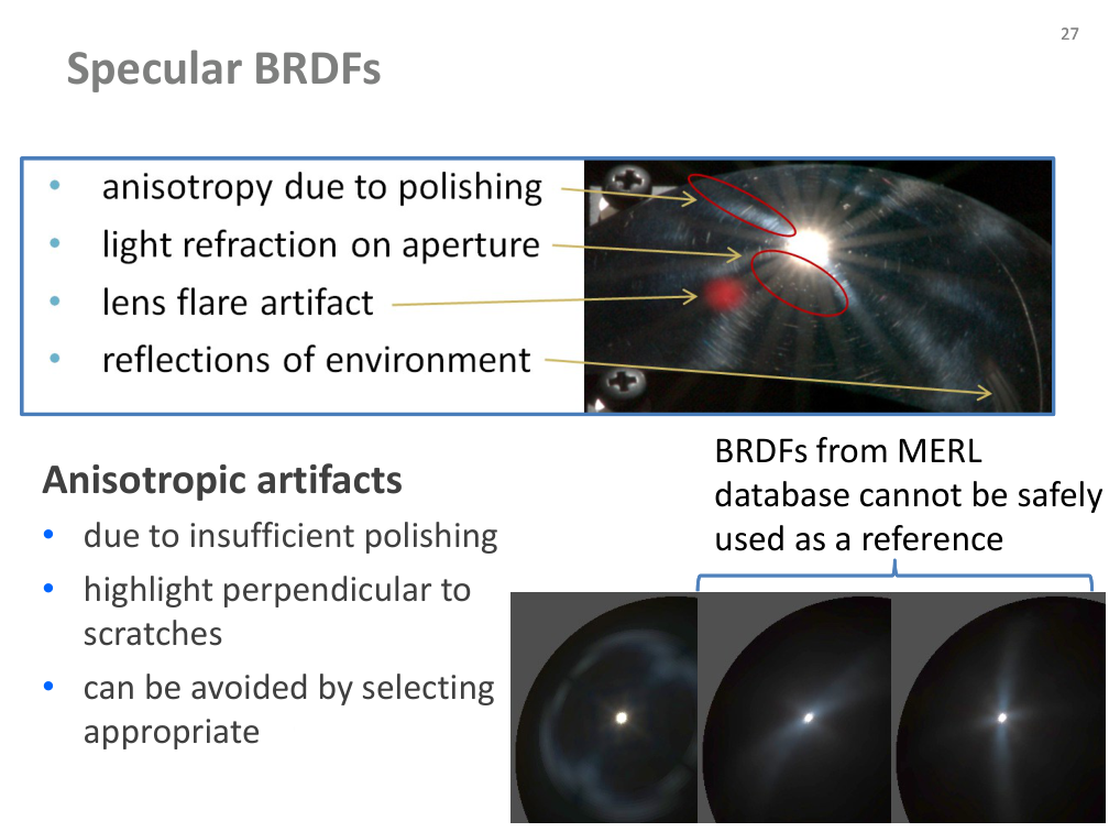
Specular materials: anisotropic artefacts

  • Insufficient polishing creates scratches and unwanted anisotropy.
  • Highlights appear perpendicular to the scratches.
  • The author discusses choosing a suitable angular slice and warns against treating MERL examples as an unquestioned reference.
Původní autorský diagram: Specular materials: anisotropic artefacts
Jiří Filip · původní diagram / ilustrace z PDF, strana 27
Původní snímek · 27Původní PDF strana 27

Jiří Filip · export PDF 30. 9. 2026 · PDF, strana 27

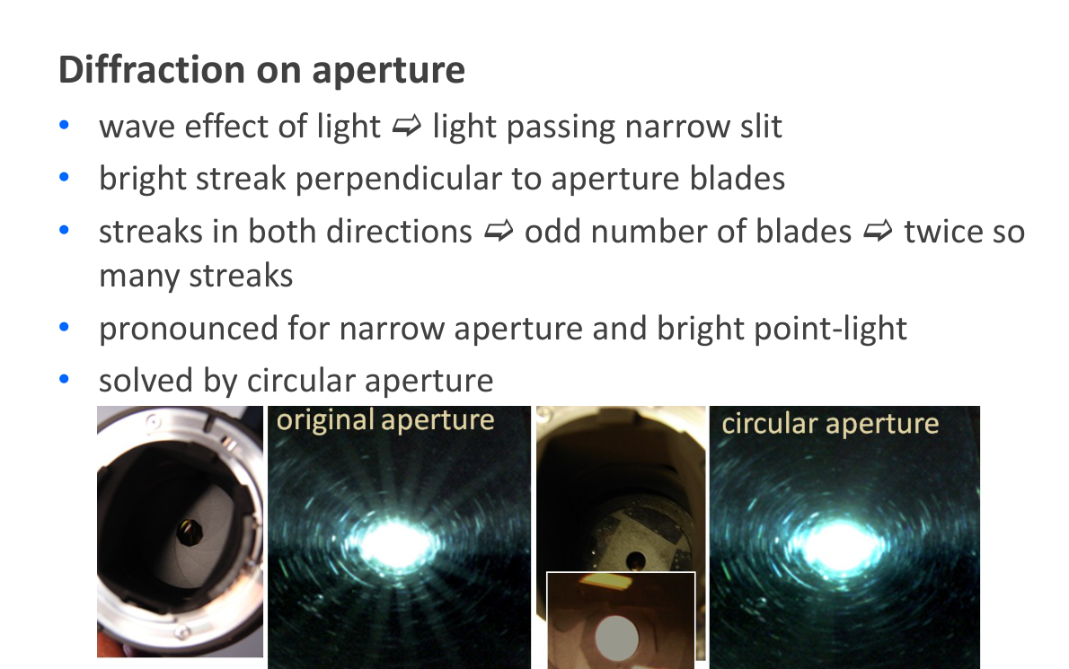
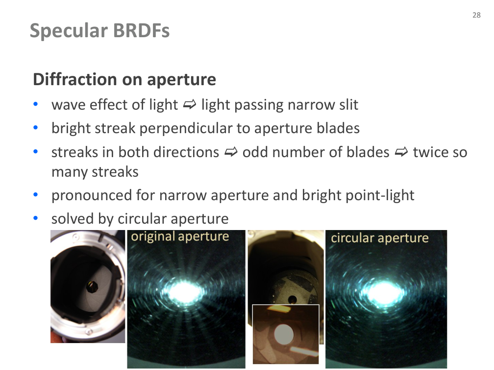
Specular materials: aperture diffraction

  • Light passing through a narrow aperture produces diffraction streaks.
  • Bright streaks are perpendicular to aperture blades; an odd blade count produces twice as many streaks in the illustrated situation.
  • The effect is pronounced with a small aperture and bright point light. The author proposes a circular aperture.
Původní autorský diagram: Specular materials: aperture diffraction
Jiří Filip · původní diagram / ilustrace z PDF, strana 28
Původní snímek · 28Původní PDF strana 28

Jiří Filip · export PDF 30. 9. 2026 · PDF, strana 28

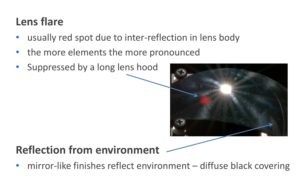
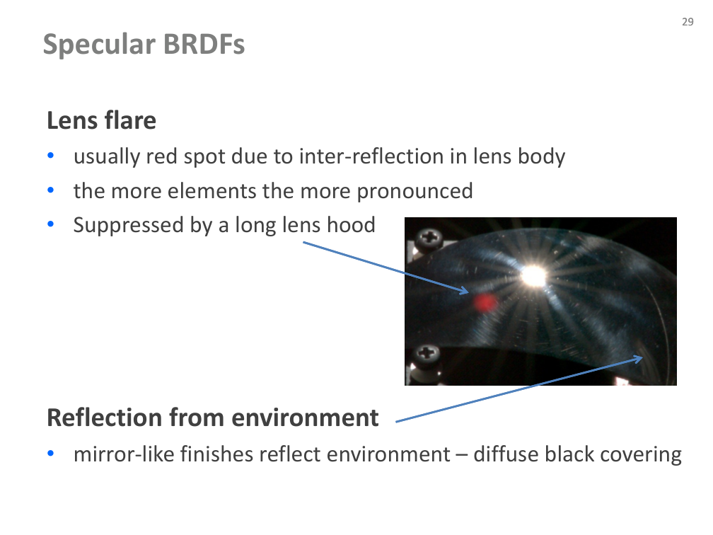
Specular materials: flare and environment

  • Lens flare arises from internal reflections; the source notes stronger effects with more lens elements and suppression using a long lens hood.
  • Mirror-like finishes reflect the measurement environment.
  • The source proposes diffuse black covering to suppress unwanted environmental reflections.
Původní autorský diagram: Specular materials: flare and environment
Jiří Filip · původní diagram / ilustrace z PDF, strana 29
Původní snímek · 29Původní PDF strana 29

Jiří Filip · export PDF 30. 9. 2026 · PDF, strana 29

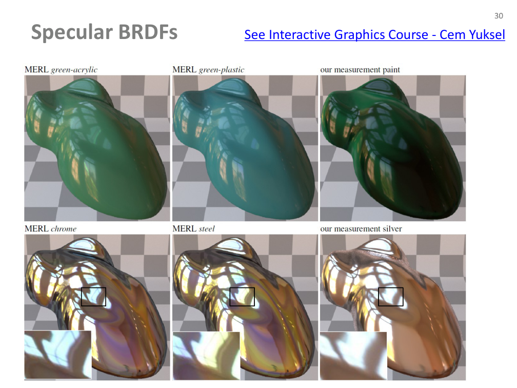
Specular materials: rendered comparison

  • Compare the appearance of highly reflective objects and their reflected environments.
  • The original slide points to Cem Yuksel’s Interactive Graphics Course; the original PDF link is preserved where present.
Původní autorský diagram: Specular materials: rendered comparison
Jiří Filip · původní diagram / ilustrace z PDF, strana 30
Původní snímek · 30Původní PDF strana 30

Jiří Filip · export PDF 30. 9. 2026 · PDF, strana 30

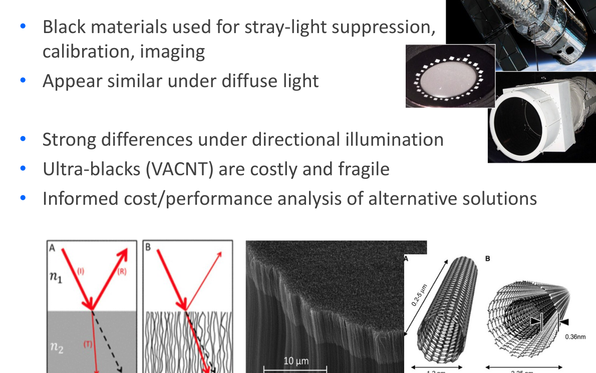
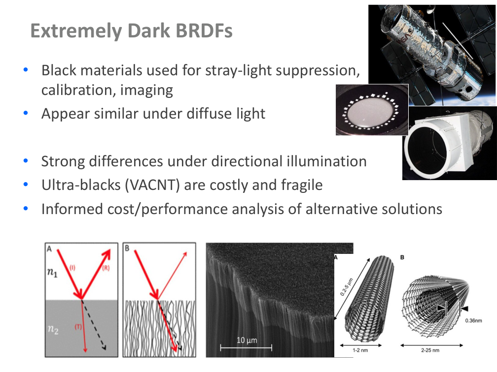
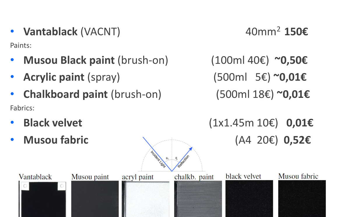
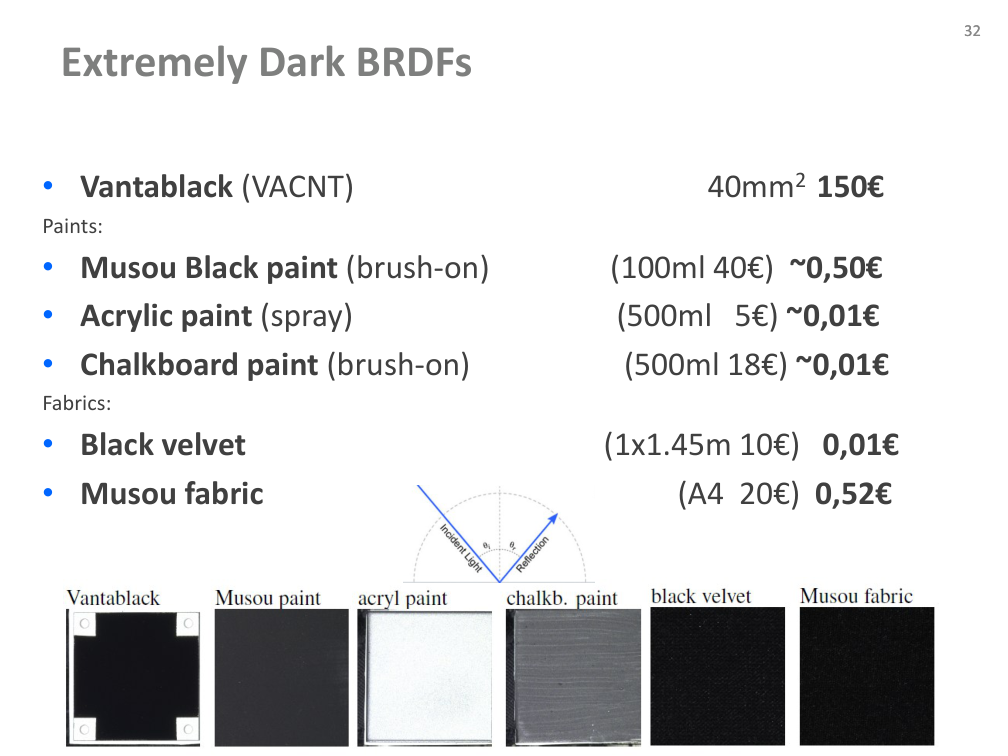
Extremely dark BRDFs: motivation

  • Black materials support stray-light suppression, calibration and imaging.
  • Materials that look similar under diffuse light can differ strongly under directional illumination.
  • VACNT ultra-black materials are costly and fragile.
  • The author motivates comparing alternative solutions by cost and performance.
Původní autorský diagram: Extremely dark BRDFs: motivation
Jiří Filip · původní diagram / ilustrace z PDF, strana 31
Původní snímek · 31Původní PDF strana 31

Jiří Filip · export PDF 30. 9. 2026 · PDF, strana 31

Extremely dark BRDFs: materials and costs

Původní ceny a parametry patří k podkladu; nejde o současnou nabídku.

  • The source compares VACNT Vantablack, Musou Black, acrylic spray paint, chalkboard paint, black velvet and Musou fabric.
  • Original price, quantity and sample-area figures remain available in the source illustration and selectable source text.
  • These are figures from the lecture material, not current prices or purchasing advice.
Původní autorský diagram: Extremely dark BRDFs: materials and costs
Jiří Filip · původní diagram / ilustrace z PDF, strana 32
Původní snímek · 32Původní PDF strana 32

Jiří Filip · export PDF 30. 9. 2026 · PDF, strana 32

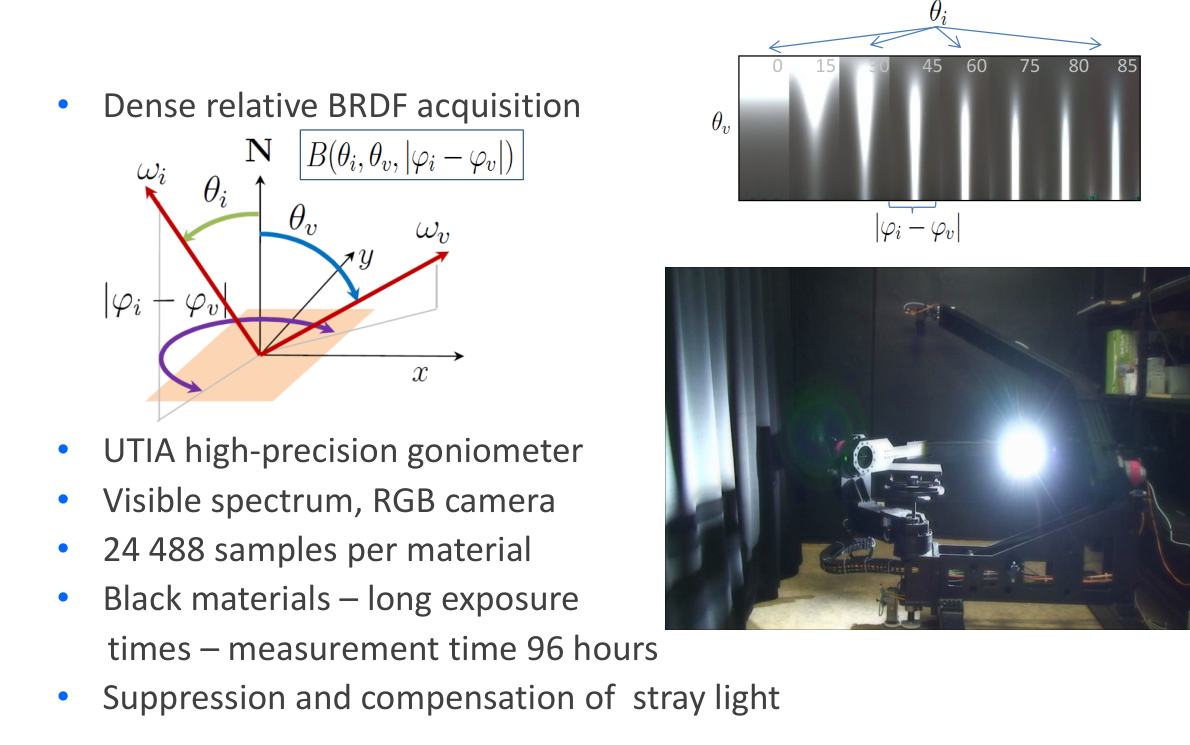
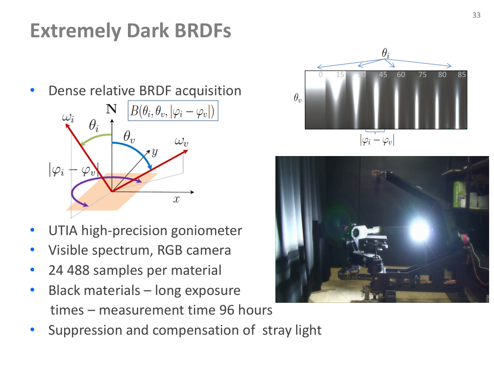
Extremely dark BRDFs: acquisition

  • UTIA high-precision goniometer; RGB camera and visible-spectrum measurements.
  • 24,488 samples per material. Long exposures for black materials led to a reported 96-hour acquisition.
  • Suppress and compensate stray light.
Původní autorský diagram: Extremely dark BRDFs: acquisition
Jiří Filip · původní diagram / ilustrace z PDF, strana 33
Původní snímek · 33Původní PDF strana 33

Jiří Filip · export PDF 30. 9. 2026 · PDF, strana 33

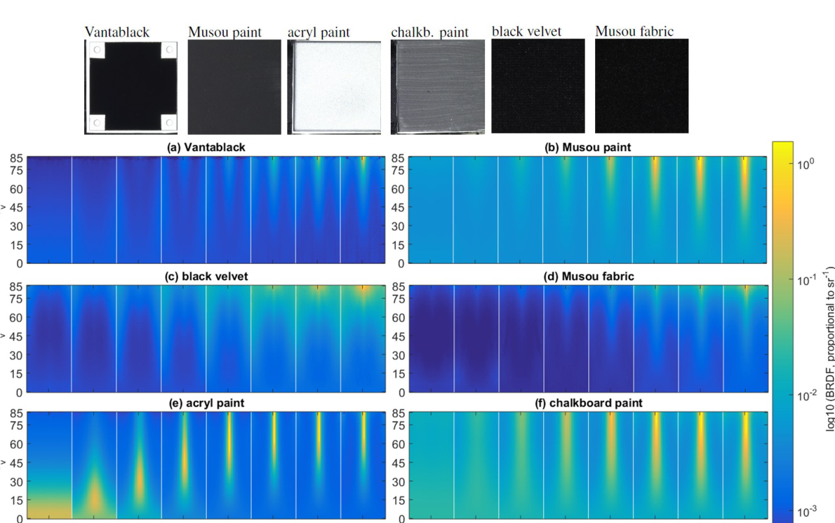
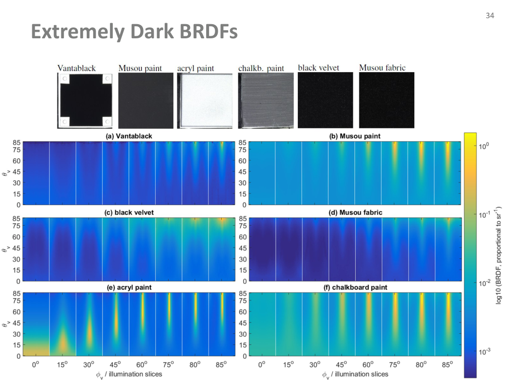
Dark materials: angular data

  • The original panel compares measured responses across several black materials.
  • Inspect the angular patterns rather than judging darkness from one photograph.
Původní autorský diagram: Dark materials: angular data
Jiří Filip · původní diagram / ilustrace z PDF, strana 34
Původní snímek · 34Původní PDF strana 34

Jiří Filip · export PDF 30. 9. 2026 · PDF, strana 34

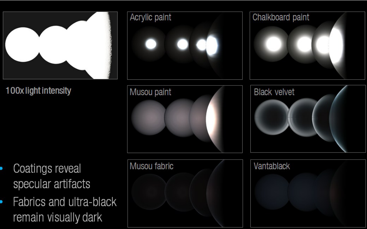
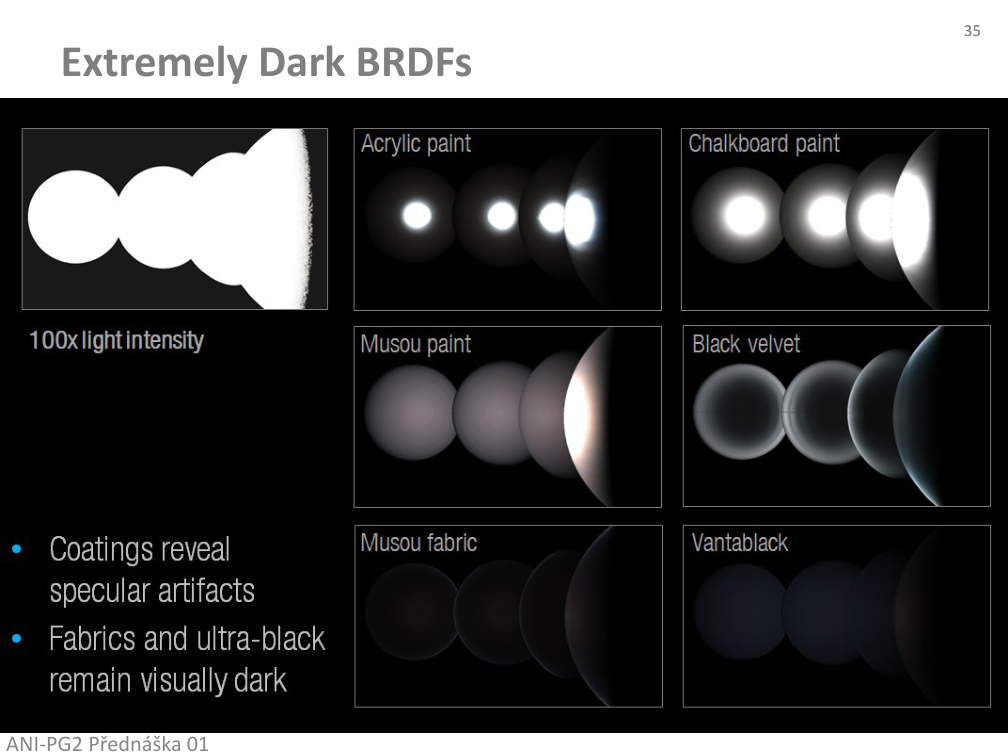
Dark materials: illumination conditions

  • Compare reflections under HDR/high-intensity and low-intensity imaging conditions.
  • Coatings and fabrics can behave differently under directional illumination.
  • Use the labelled source panels to identify material and acquisition conditions.
Původní autorský diagram: Dark materials: illumination conditions
Jiří Filip · původní diagram / ilustrace z PDF, strana 35
Původní snímek · 35Původní PDF strana 35

Jiří Filip · export PDF 30. 9. 2026 · PDF, strana 35

Dark materials: integrated quantities

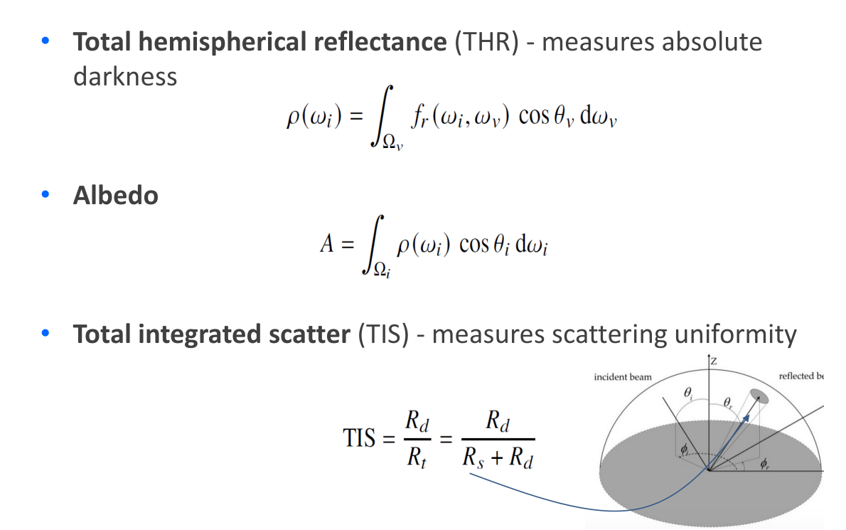
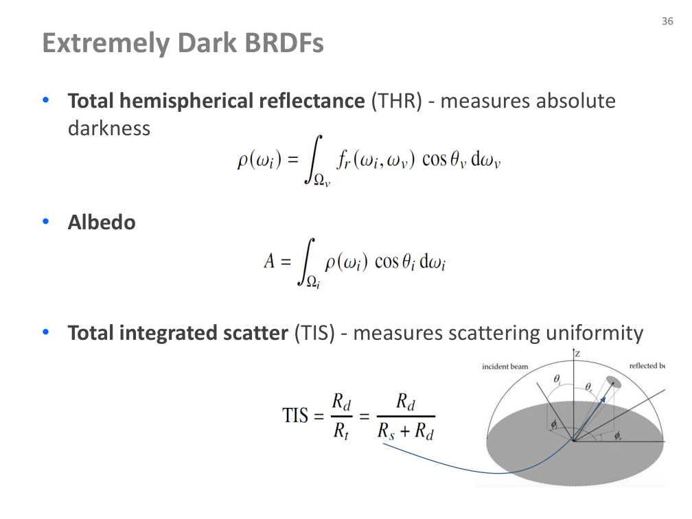
  • Total hemispherical reflectance: integrate fᵣ(ωᵢ, ωᵥ) cos θᵥ over outgoing solid angle.
  • Albedo in the source: integrate ρ(ωᵢ) cos θᵢ over incident directions.
  • Total integrated scatter: TIS = Rᵈ / Rᵗ = Rᵈ / (Rˢ + Rᵈ).
  • The author’s original integral notation and geometry are preserved alongside the HTML explanation.
Původní autorský diagram: Dark materials: integrated quantities
Jiří Filip · původní diagram / ilustrace z PDF, strana 36
Původní snímek · 36Původní PDF strana 36

Jiří Filip · export PDF 30. 9. 2026 · PDF, strana 36

Dark materials: comparing metrics

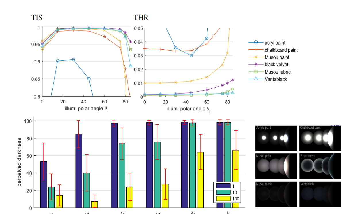
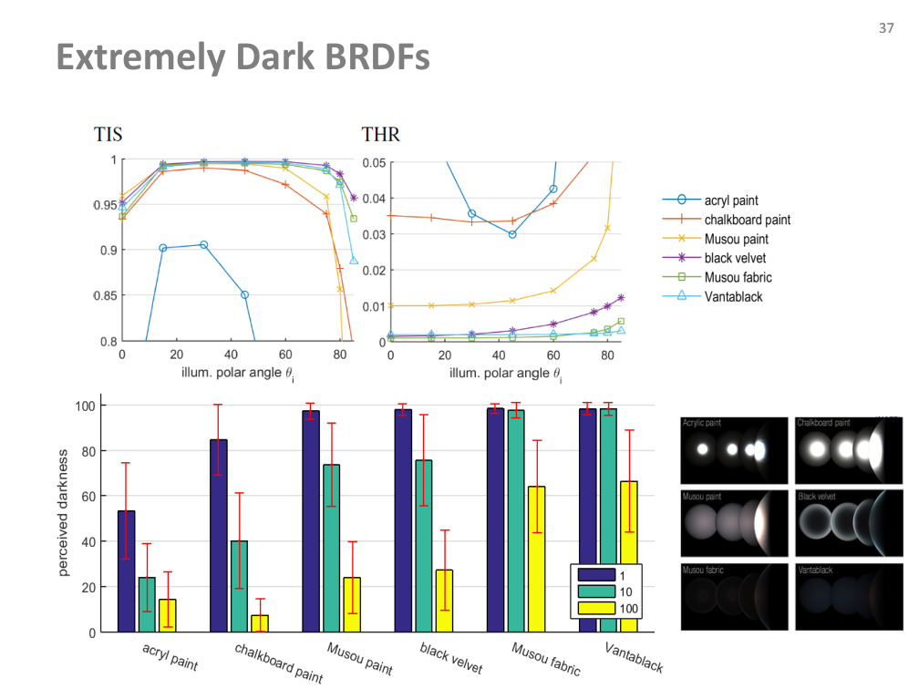
  • Compare the source plots of angular and integrated measurements across the material samples.
  • Darkness and scattering distribution answer different questions.
  • The measured curves are original author data; the sampling model in this web is a separate synthetic example.
Původní autorský diagram: Dark materials: comparing metrics
Jiří Filip · původní diagram / ilustrace z PDF, strana 37
Původní snímek · 37Původní PDF strana 37

Jiří Filip · export PDF 30. 9. 2026 · PDF, strana 37

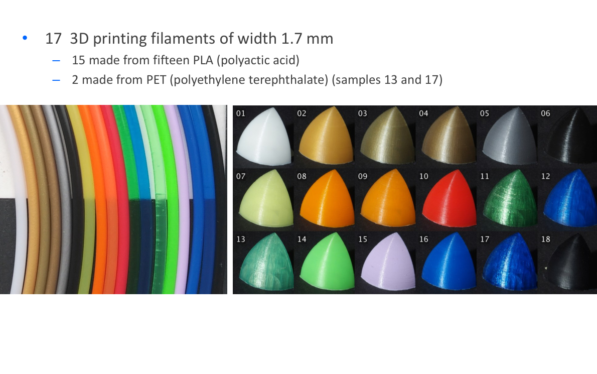
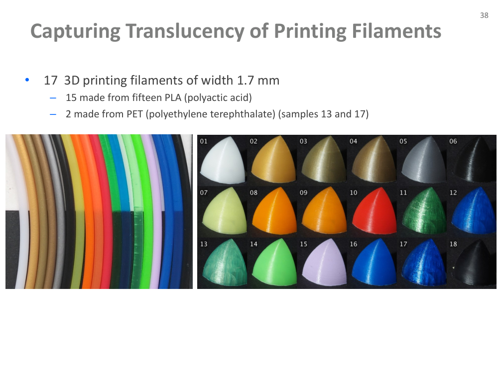
Translucency of printing filaments

  • 17 filament samples of diameter 1.7 mm.
  • 15 PLA samples; PET samples 13 and 17.
  • The source photograph identifies the coloured specimens.
Původní autorský diagram: Translucency of printing filaments
Jiří Filip · původní diagram / ilustrace z PDF, strana 38
Původní snímek · 38Původní PDF strana 38

Jiří Filip · export PDF 30. 9. 2026 · PDF, strana 38

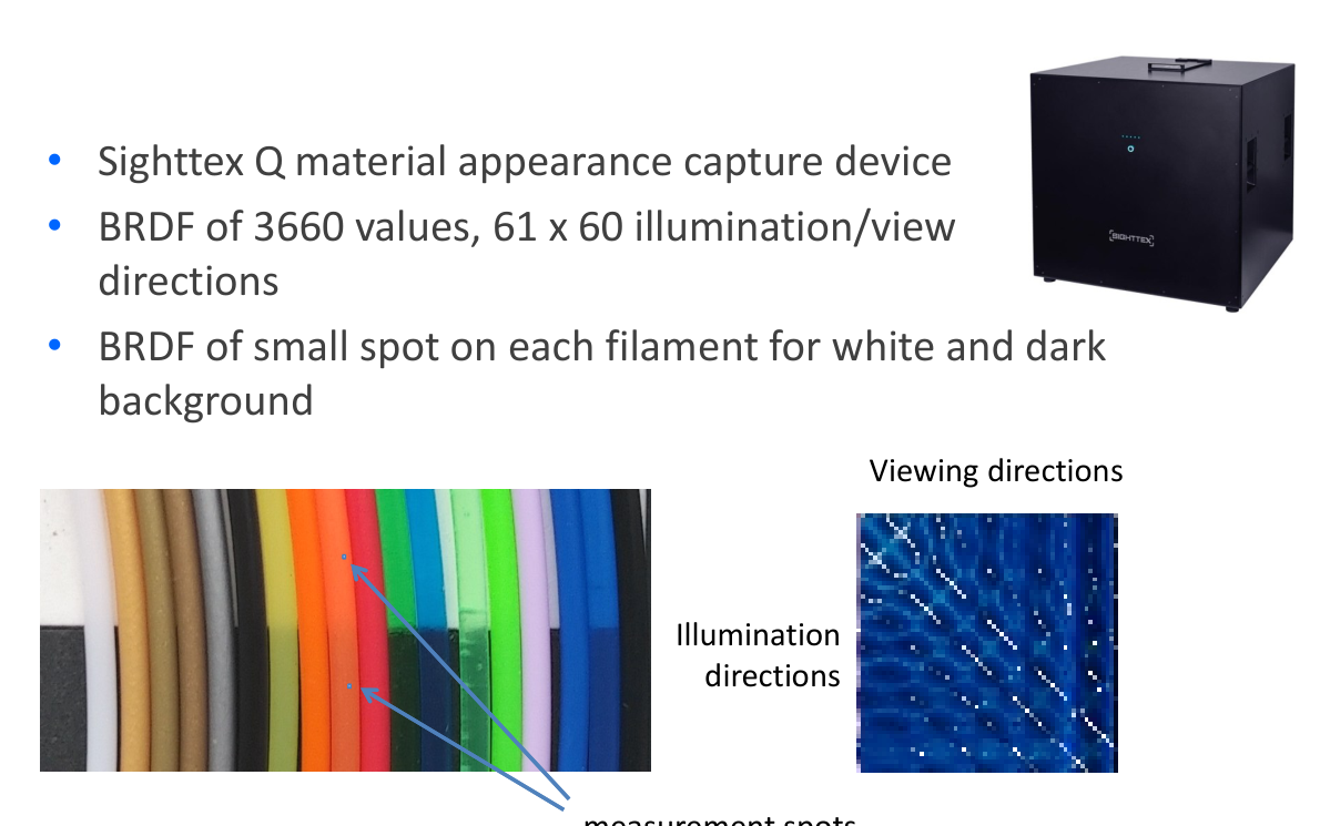
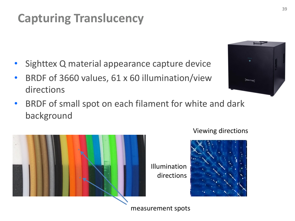
Translucency: capture arrangement

  • Sighttex Q material-appearance capture device.
  • 3,660 BRDF values: 61 × 60 illumination/view directions.
  • Measure a small spot on each filament against both white and dark backgrounds.
Původní autorský diagram: Translucency: capture arrangement
Jiří Filip · původní diagram / ilustrace z PDF, strana 39
Původní snímek · 39Původní PDF strana 39

Jiří Filip · export PDF 30. 9. 2026 · PDF, strana 39

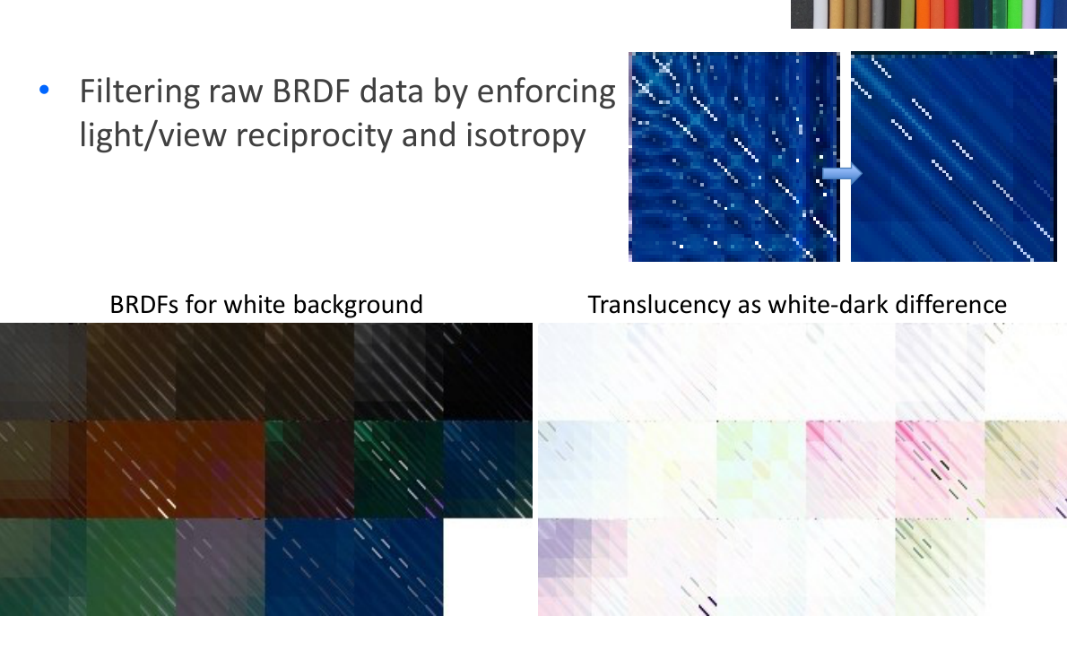
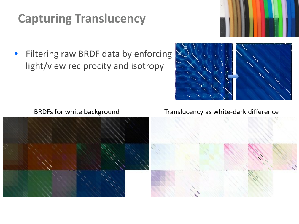
Translucency: filtering and background difference

  • Filter raw BRDF data using light/view reciprocity and isotropy.
  • The source illustrates BRDFs against a white background and a translucency proxy from the white–dark difference.
  • Keep the background and filtering assumptions visible when interpreting the difference.
Původní autorský diagram: Translucency: filtering and background difference
Jiří Filip · původní diagram / ilustrace z PDF, strana 40
Původní snímek · 40Původní PDF strana 40

Jiří Filip · export PDF 30. 9. 2026 · PDF, strana 40

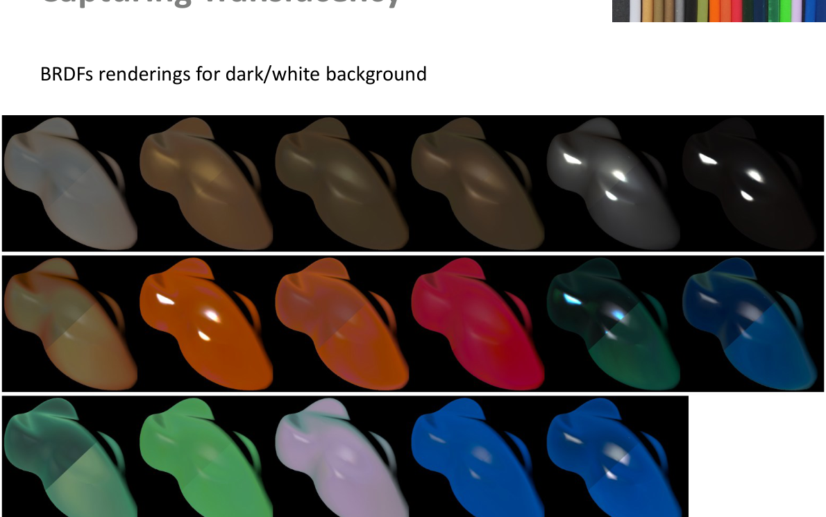
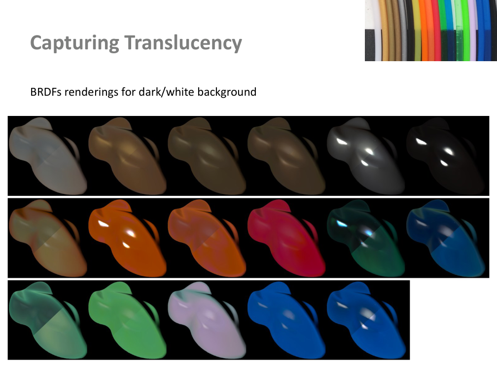
Translucency: appearance renderings

  • Compare the original BRDF renderings against dark and white backgrounds.
  • The source panel shows how the same filament samples change under the two capture conditions.
Původní autorský diagram: Translucency: appearance renderings
Jiří Filip · původní diagram / ilustrace z PDF, strana 41
Původní snímek · 41Původní PDF strana 41

Jiří Filip · export PDF 30. 9. 2026 · PDF, strana 41

References: BRDF measurement I

References
BRDF measurement
•
Murray-Coleman, J., Smith, A.: The automated measurement of BRDFs and
their application to luminaire modeling. Journal of the Illuminating
Engineering Society pp. 87–99 (1990)
•
White, D.R., Saunders, P., Bonsey, S.J., van de Ven, J., Edgar, H.:
Reflectometer for measuring the bidirectional reflectance of rough surfaces.
Journal of Applied Optics 37, 3450–3454 (1998)
•
Ward, G.: Measuring and modeling anisotropic reflection. Computer
Graphics 26(2) (1992)
•
Dana, K.: BRDF/BTF measurement device. ICCV 2001, vol. 2, pp. 460–466
(2001)
•
Mukaigawa, Y., Sumino, K., Yagi, Y.: Multiplexed illumination for measuring
BRDF using an ellipsoidal mirror and a projector, ACCV’07, pp. 246–257
•
Ghosh, A., Achutha, S., Heidrich, W., O’Toole, M.: BRDF acquisition with
basis illumination. ICCV 2007, 1–8 (2007)
Původní snímek · 42Původní PDF strana 42

Jiří Filip · export PDF 30. 9. 2026 · PDF, strana 42

References: BRDF measurement II

References
BRDF measurement
•
Lu, R., Koenderink, J.J., Kappers, A.M.L.: Optical properties (bidirectional
reflectance distribution functions) of velvet. Applied Optics 37, 5974 5984
(1998)
•
Ngan, A., Durand, F., Matusik, W.: Experimental analysis of BRDF models.
Eurographics Symposium on Rendering 2005 pp. 117–126 (2005)
•
Marschner, S.R., Westin, S.H., Lafortune, E.P.F., Torrance, K.E.: Image-based
biderectional reflectance distribution function measurement. Applied Optics
39 (2000)
•
Matusik,W., Pfister H.P. Brand, M., McMillan, L.: Image-based BRDF
measurement including human skin. In: Proceedings of 10th
EurographicsWorkshop on Rendering, pp. 139–152 (2003)
•
Ben-Ezra, M., Wang, J., Wilburn, B., Li, X., Ma, L.: An LED-only BRDF
measurement device. CVPR 2008, 1–8
•
Lan, Y., Dong, Y.,Wang, J., Tong, X., Guo, B.: Condenser-based instant
reflectometry. Computer Graphics Forum 29(7), 2091–2098 (2010)
Původní snímek · 43Původní PDF strana 43

Jiří Filip · export PDF 30. 9. 2026 · PDF, strana 43

References: BSSRDF measurement

References


BSSRDF measurements
•
Nicodemus, F., J.C., R., Hsia, J., Ginsburg, I., Limperis, T.: Geometrical
considerations and nomenclature for reflectance. NBS Monograph 160,
National Bureau of Standards, U.S. Department of Commerce, Washington,
D. C. pp. 1–52 (1977)
•
Goesele, M., Lensch, H.P.A., Lang, J., Fuchs, C., Seidel, H.P.: Disco: acquisition
of translucent objects. ACM Trans. Graph. 23, 835–844 (2004)
•
Tong, X., Wang, J., Lin, S., Guo, B., Shum, H.Y.: Modeling and rendering of
quasihomogeneous materials. In: ACM SIGGRAPH 2005 Papers, SIGGRAPH
’05, pp. 1054–1061. ACM, New York, NY, USA (2005)
•
Jensen, H.W., Marschner, S.R., Levoy, M., Hanrahan, P.: A practical model for
subsurface light transport. In: Proceedings of the 28th annual conference on
Computer graphics and interactive techniques, SIGGRAPH ’01, pp. 511–518.
ACM, New York, NY, USA (2001)
Původní snímek · 44Původní PDF strana 44

Jiří Filip · export PDF 30. 9. 2026 · PDF, strana 44

References: component separation and volumes

References


BSSRDF - diffuse/specular components separation
•
Shafer, S.A.: Using color to separate reflection components. Color Research
& Application 10(4), 210–218 (1985)
•
Nayar, S.K., Fang, X.S., Boult, T.: Separation of reflection components using
color and polarization. International Journal of Computer Vision 21, 163–
186 (1997).
•
Nayar, S.K., Krishnan, G., Grossberg, M.D., Raskar, R.: Fast separation of
direct and global components of a scene using high frequency illumination.
ACM Trans. Graph. 25, 935–944 (2006)
Volumetric Model Acquisition
•
S. Zhao,W. Jakob, S. Marschner, K. Bala, Building volumetric appearance
models of fabric using micro CT imaging, ACM Trans. Graph., 30(4), 2011
Původní snímek · 45Původní PDF strana 45

Jiří Filip · export PDF 30. 9. 2026 · PDF, strana 45

References: BRDF representation

References
BRDF representation
•
Rusinkiewicz, S.M., A new change of variables for efficient BRDF
representation, Rendering techniques' 98, 1998, pp. 11,
•
Havran V., Filip J., Myzskowski K., Bidirectional Texture Function Compression
based on Multi-Level Vector Quantization. Computer Graphics Forum, vol.
29, no. 1, pp. 175-190, March 2010
Původní snímek · 46Původní PDF strana 46

Jiří Filip · export PDF 30. 9. 2026 · PDF, strana 46

Obsah přednášky

Poznámky

Původní text PDF

Vzorkování odrazivosti · GRAFIT

Syntetický 1D řez: porovnejte rovnoměrné a adaptivní vzorkování úzkého vrcholu.

Didaktický doplněk GRAFIT: normalizovaná Gaussova křivka, není fyzikální BRDF ani změřený materiál. Adaptivní metoda zde vybírá interval podle chyby lineární interpolace v jeho středu a potřebuje další zkušební vyhodnocení; stejný počet uchovaných vzorků neznamená stejný čas měření. Není to implementace metody CVPR 2013. Chyba se počítá na syntetické referenční mřížce.